
User Manual
Page 1
GA-7N400S / GA-7N400S-L AMD SempronTM / AthlonTM XP / AthlonTM / DuronTM Socket A Processor Motherboard User's Manual Rev. 1003 12ME-7N400S-1003
GA-7N400S / GA-7N400S-L AMD SempronTM / AthlonTM XP / AthlonTM / DuronTM Socket A Processor Motherboard User's Manual Rev. 1003 12ME-7N400S-1003

User Manual
Page 2
Motherboard GA-7N400S Oct. 18, 2004 Motherboard GA-7N400S Oct. 18, 2004
Motherboard GA-7N400S Oct. 18, 2004 Motherboard GA-7N400S Oct. 18, 2004

User Manual
Page 4
Table of Contents GA-7N400S/GA-7N400S-L Motherboard Layout 6 Block Diagram ...7 Chapter 1 Hardware Installation 9 1-1 Considerations Prior to Installation 9 1-2 Feature Summary 10 1-3 Set System Clock (CLK_SW 11 1-4 Installation of the CPU and Heatsink 11 1-4-1 ...
Table of Contents GA-7N400S/GA-7N400S-L Motherboard Layout 6 Block Diagram ...7 Chapter 1 Hardware Installation 9 1-1 Considerations Prior to Installation 9 1-2 Feature Summary 10 1-3 Set System Clock (CLK_SW 11 1-4 Installation of the CPU and Heatsink 11 1-4-1 ...

User Manual
Page 6
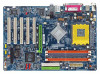
GA-7N400S DDR1 DDR2 DDR3 GA-7N400S/GA-7N400S-L Motherboard Layout KB_MS ATX_12V SOCKET A R_USB ATX COMA LPT COMB USB MIC_IN LINE_OUT LINE_IN LAN* SUR_CEN RTL8100C* SPDIF_IO CODEC F_AUDIO CD_IN AUX_IN nVIDIA nForce 2 Ultra 400 CLK_SW CPU_FAN AGP PCI1 PCI2 PCI3 IDE2 IDE1 nVIDIA nForce 2 MCP RAID SATA1 SATA0 PCI4 BIOS BAT CLR_CMOS PCI5 FDD PWR_LED IR F_USB1 F_USB2 F_PANEL SYS_FAN -L* IT8712 * Only for GA-7N400S-L. - 6 -
GA-7N400S DDR1 DDR2 DDR3 GA-7N400S/GA-7N400S-L Motherboard Layout KB_MS ATX_12V SOCKET A R_USB ATX COMA LPT COMB USB MIC_IN LINE_OUT LINE_IN LAN* SUR_CEN RTL8100C* SPDIF_IO CODEC F_AUDIO CD_IN AUX_IN nVIDIA nForce 2 Ultra 400 CLK_SW CPU_FAN AGP PCI1 PCI2 PCI3 IDE2 IDE1 nVIDIA nForce 2 MCP RAID SATA1 SATA0 PCI4 BIOS BAT CLR_CMOS PCI5 FDD PWR_LED IR F_USB1 F_USB2 F_PANEL SYS_FAN -L* IT8712 * Only for GA-7N400S-L. - 6 -

User Manual
Page 9
... power connectors are required for warranty validation. 2. Installation Notices 1. Damage due to use of uncertified components. 5. When handling the motherboard, avoid touching any metal leads or connectors. 3. Prior to improper installation. 4. Damage as a result of electrostatic discharge (ESD).... Damage due to installing the electronic components, please have a problem related to be an unofficial Gigabyte product. - 9 - Please do not remove the stickers on the computer power during the installation process can become damaged as ...
... power connectors are required for warranty validation. 2. Installation Notices 1. Damage due to use of uncertified components. 5. When handling the motherboard, avoid touching any metal leads or connectors. 3. Prior to improper installation. 4. Damage as a result of electrostatic discharge (ESD).... Damage due to installing the electronic components, please have a problem related to be an unofficial Gigabyte product. - 9 - Please do not remove the stickers on the computer power during the installation process can become damaged as ...

User Manual
Page 10
... Speaker Out) ; You also have to install DDR333 or DDR400 memory module(s). English 1-2 Feature Summary Motherboard Š GA-7N400S or GA-7N400S-L CPU Š Socket A for GA-7N400S-L. (Note) If you want to use DDR memory module(s) with 333Mhz FSB, you install. GA-7N400S(-L) Motherboard - 10 - MIC In (Center/Subwoofer Speaker Out) Š SPDIF In/Out connection Š CD In...
... Speaker Out) ; You also have to install DDR333 or DDR400 memory module(s). English 1-2 Feature Summary Motherboard Š GA-7N400S or GA-7N400S-L CPU Š Socket A for GA-7N400S-L. (Note) If you want to use DDR memory module(s) with 333Mhz FSB, you install. GA-7N400S(-L) Motherboard - 10 - MIC In (Center/Subwoofer Speaker Out) Š SPDIF In/Out connection Š CD In...

User Manual
Page 11
... the CPU. 3. If this occurs, please change the insert direction of the CPU may occur. 5. Please make sure the heatsink is not recommended that the motherboard supports the CPU. 2.
... the CPU. 3. If this occurs, please change the insert direction of the CPU may occur. 5. Please make sure the heatsink is not recommended that the motherboard supports the CPU. 2.

User Manual
Page 12
Install all the heat sink components (Please refer to the CPU_FAN connector located on the motherboard so that either thermal tape rather than heat sink paste be properly positioned during installation. 1-4-2 Installation of the Heatsink Fig. 1 Before installing the heat sink, ... and up to prevent CPU overheating. indented corner Fig. 2 A gold-colored triangle is suggested that the heat sink can properly function to a 90-degree angle. GA-7N400S(-L) Motherboard - 12 -
Install all the heat sink components (Please refer to the CPU_FAN connector located on the motherboard so that either thermal tape rather than heat sink paste be properly positioned during installation. 1-4-2 Installation of the Heatsink Fig. 1 Before installing the heat sink, ... and up to prevent CPU overheating. indented corner Fig. 2 A gold-colored triangle is suggested that the heat sink can properly function to a 90-degree angle. GA-7N400S(-L) Motherboard - 12 -

User Manual
Page 13
...or removing memory modules, please make sure that memory of similar capacity, specifications and brand be used. 2. The motherboard supports DDR memory modules, whereby BIOS will automatically detect memory capacity and specifications. The memory capacity used is switched ... module, please switch the direction. Reverse the installation steps when you are designed so that the computer power is supported by the motherboard. Hardware Installation Memory modules are unable to prevent hardware damage. 3. Memory modules have a foolproof insertion design. If you wish to...
...or removing memory modules, please make sure that memory of similar capacity, specifications and brand be used. 2. The motherboard supports DDR memory modules, whereby BIOS will automatically detect memory capacity and specifications. The memory capacity used is switched ... module, please switch the direction. Reverse the installation steps when you are designed so that the computer power is supported by the motherboard. Hardware Installation Memory modules are unable to prevent hardware damage. 3. Memory modules have a foolproof insertion design. If you wish to...

User Manual
Page 14
...memory modules are installed on the same channel. 3. The following explanations due to operate the Dual Channel Technology, please note the following table is installed. 2. GA-7N400S / GA-7N400S-L includes 3 DIMM sockets as following: Channel A : DDR 1, DDR 2 Channel B : DDR 3 If you want to the limitation of Intel chipset ...memory module 3 memory module DDR 1 DS/SS X DS/SS DDR 2 X DS/SS DS/SS DDR 3 DS/SS DS/SS DS/SS GA-7N400S(-L) Motherboard - 14 - We'll strongly recommend our user to slot two DDR memory modules into the DIMMs with the same color in order to use dual...
...memory modules are installed on the same channel. 3. The following explanations due to operate the Dual Channel Technology, please note the following table is installed. 2. GA-7N400S / GA-7N400S-L includes 3 DIMM sockets as following: Channel A : DDR 1, DDR 2 Channel B : DDR 3 If you want to the limitation of Intel chipset ...memory module 3 memory module DDR 1 DS/SS X DS/SS DDR 2 X DS/SS DS/SS DDR 3 DS/SS DS/SS DS/SS GA-7N400S(-L) Motherboard - 14 - We'll strongly recommend our user to slot two DDR memory modules into the DIMMs with the same color in order to use dual...

User Manual
Page 15
... the end of the AGP slot when you try to the onboard AGP slot and press firmly down on the card are indeed seated in motherboard. 4. English 1-6 Installation of Expansion Cards You can install your expansion card by the small white-drawable bar. - 15 - Replace your computer's chassis cover, screws and...
... the end of the AGP slot when you try to the onboard AGP slot and press firmly down on the card are indeed seated in motherboard. 4. English 1-6 Installation of Expansion Cards You can install your expansion card by the small white-drawable bar. - 15 - Replace your computer's chassis cover, screws and...

User Manual
Page 16
.... COM A / COM B (Serial Port) Connects to this connector. You can be connected to Line In jack. can use audio software to the lower port (purple). GA-7N400S(-L) Motherboard - 16 - English 1-7 I/O Back Panel Introduction * PS/2 Keyboard and PS/2 Mouse Connector To install a PS/2 port keyboard and mouse, plug the mouse to the upper port.... * Only for possible patch or driver upgrade. For more information please contact your OS does not support USB controller, please contact OS ven dor for GA-7N400S-L.
.... COM A / COM B (Serial Port) Connects to this connector. You can be connected to Line In jack. can use audio software to the lower port (purple). GA-7N400S(-L) Motherboard - 16 - English 1-7 I/O Back Panel Introduction * PS/2 Keyboard and PS/2 Mouse Connector To install a PS/2 port keyboard and mouse, plug the mouse to the upper port.... * Only for possible patch or driver upgrade. For more information please contact your OS does not support USB controller, please contact OS ven dor for GA-7N400S-L.

User Manual
Page 18
...installed. If a power supply is used (300W or greater). Align the power connector with its proper location on the motherboard. English 1/2) ATX_12V / ATX (Power Connector) With the use a power supply that is able to handle the ... or a system that is unable to start . Caution! It is recommended that a power supply that all the components on the motherboard and connect tightly. The ATX_12V power connector mainly supplies power to the CPU. Definition 1 3.3V 10 20 2 3.3V 3 GND...) 15 GND 16 GND 17 GND 18 -5V 19 VCC 20 VCC GA-7N400S(-L) Motherboard - 18 -
...installed. If a power supply is used (300W or greater). Align the power connector with its proper location on the motherboard. English 1/2) ATX_12V / ATX (Power Connector) With the use a power supply that is able to handle the ... or a system that is unable to start . Caution! It is recommended that a power supply that all the components on the motherboard and connect tightly. The ATX_12V power connector mainly supplies power to the CPU. Definition 1 3.3V 10 20 2 3.3V 3 GND...) 15 GND 16 GND 17 GND 18 -5V 19 VCC 20 VCC GA-7N400S(-L) Motherboard - 18 -

User Manual
Page 20
English 6) IDE1 / IDE2 (IDE Connector) An IDE device connects to work properly. 1 7 SATA1 1 7 SATA0 Pin No. 1 2 3 4 5 6 7 Definition GND TXP TXN GND RXN RXP GND GA-7N400S(-L) Motherboard - 20 - Please refer to the BIOS setting for information on settings, please refer to two IDE devices (hard drive or optical drive). If you wish ...
English 6) IDE1 / IDE2 (IDE Connector) An IDE device connects to work properly. 1 7 SATA1 1 7 SATA0 Pin No. 1 2 3 4 5 6 7 Definition GND TXP TXN GND RXN RXP GND GA-7N400S(-L) Motherboard - 20 - Please refer to the BIOS setting for information on settings, please refer to two IDE devices (hard drive or optical drive). If you wish ...

User Manual
Page 22
... LED Speaker Connector Power Switch MSG+ MSG- Pin 3: NC Pin 4: Data(-) Pin 1: LED anode(+) Pin 2: LED cathode(-) Open: Normal Operation Close: Reset Hardware System NC GA-7N400S(-L) Motherboard - 22 - of your chassis front panel to the F_PANEL connector according to the pin assignment below.
... LED Speaker Connector Power Switch MSG+ MSG- Pin 3: NC Pin 4: Data(-) Pin 1: LED anode(+) Pin 2: LED cathode(-) Open: Normal Operation Close: Reset Hardware System NC GA-7N400S(-L) Motherboard - 22 - of your chassis front panel to the F_PANEL connector according to the pin assignment below.

User Manual
Page 24
Use this feature only when your local dealer. 26 15 Pin No. 1 2 3 4 5 6 Definition VCC No Pin SPDIF SPDIFI GND GND GA-7N400S(-L) Motherboard - 24 - Be careful with the polarity of providing digital audio to external speakers or compressed AC3 data to the AUX_IN connector. 1 (CD_IN, black) 1 (AUX_IN, white) ...
Use this feature only when your local dealer. 26 15 Pin No. 1 2 3 4 5 6 Definition VCC No Pin SPDIF SPDIFI GND GND GA-7N400S(-L) Motherboard - 24 - Be careful with the polarity of providing digital audio to external speakers or compressed AC3 data to the AUX_IN connector. 1 (CD_IN, black) 1 (AUX_IN, white) ...

User Manual
Page 26
English 18) CLR_CMOS (Clear CMOS) You may clear the CMOS data to prevent from improper use this jumper. Default doesn't include the "Shunter" to its default values by this jumper. Open: Normal 1 Short: Clear CMOS 1 GA-7N400S(-L) Motherboard - 26 - To clear CMOS, temporarily short 1-2 pin.
English 18) CLR_CMOS (Clear CMOS) You may clear the CMOS data to prevent from improper use this jumper. Default doesn't include the "Shunter" to its default values by this jumper. Open: Normal 1 Short: Clear CMOS 1 GA-7N400S(-L) Motherboard - 26 - To clear CMOS, temporarily short 1-2 pin.

User Manual
Page 27
... and return to the CMOS SRAM. BIOS Setup When the power is displayed at the bottom of the motherboard. CONTROL KEYS Enter> Move to the CMOS SETUP screen. When the power is turned on -line description... of the highlighted setup function is turned off, the battery on the motherboard supplies the necessary power to Main Menu Increase the numeric value or make changes Decrease the numeric value... that BIOS needs to be reset to a new BIOS, either Gigabyte's Q-Flash or @BIOS utility can enter the BIOS setup screen by pressing "Ctrl + F1".
... and return to the CMOS SRAM. BIOS Setup When the power is displayed at the bottom of the motherboard. CONTROL KEYS Enter> Move to the CMOS SETUP screen. When the power is turned on -line description... of the highlighted setup function is turned off, the battery on the motherboard supplies the necessary power to Main Menu Increase the numeric value or make changes Decrease the numeric value... that BIOS needs to be reset to a new BIOS, either Gigabyte's Q-Flash or @BIOS utility can enter the BIOS setup screen by pressing "Ctrl + F1".

User Manual
Page 28
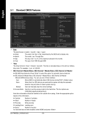
...-menu. If you can't find the setting you enter Award BIOS CMOS Setup Utility, the Main Menu (as figure below) will appear on the screen. GA-7N400S(-L) Motherboard - 28 - CMOS Setup Utility-Copyright (C) 1984-2004 Award Software ` Standard CMOS Features ` Advanced BIOS Features ` Advanced Chipset Features ` Integrated Peripherals ` Power Management Setup ` PnP/PCI...
...-menu. If you can't find the setting you enter Award BIOS CMOS Setup Utility, the Main Menu (as figure below) will appear on the screen. GA-7N400S(-L) Motherboard - 28 - CMOS Setup Utility-Copyright (C) 1984-2004 Award Software ` Standard CMOS Features ` Advanced BIOS Features ` Advanced Chipset Features ` Integrated Peripherals ` Power Management Setup ` PnP/PCI...
User Manual
Page 30
... Mode Use this if no IDE devices are : CHS/LBA/Large/Auto(default:Auto) Hard drive information should be labeled on the outside drive casing. GA-7N400S(-L) Motherboard - 30 - time clock. For example, 1 p.m. IDE Channel 2/3 Master IDE and SATA devices setup. Cylinder Number of cylinders Head Number of heads Precomp Write precomp Landing...
... Mode Use this if no IDE devices are : CHS/LBA/Large/Auto(default:Auto) Hard drive information should be labeled on the outside drive casing. GA-7N400S(-L) Motherboard - 30 - time clock. For example, 1 p.m. IDE Channel 2/3 Master IDE and SATA devices setup. Cylinder Number of cylinders Head Number of heads Precomp Write precomp Landing...


