
User Manual
Page 1
GA-7N400S / GA-7N400S-L AMD SempronTM / AthlonTM XP / AthlonTM / DuronTM Socket A Processor Motherboard User's Manual Rev. 1003 12ME-7N400S-1003
GA-7N400S / GA-7N400S-L AMD SempronTM / AthlonTM XP / AthlonTM / DuronTM Socket A Processor Motherboard User's Manual Rev. 1003 12ME-7N400S-1003

User Manual
Page 2
Motherboard GA-7N400S Oct. 18, 2004 Motherboard GA-7N400S Oct. 18, 2004
Motherboard GA-7N400S Oct. 18, 2004 Motherboard GA-7N400S Oct. 18, 2004

User Manual
Page 4
Table of Contents GA-7N400S/GA-7N400S-L Motherboard Layout 6 Block Diagram ...7 Chapter 1 Hardware Installation 9 1-1 Considerations Prior to Installation 9 1-2 Feature Summary 10 1-3 Set System Clock (CLK_SW 11 1-4 Installation of the CPU and Heatsink ...
Table of Contents GA-7N400S/GA-7N400S-L Motherboard Layout 6 Block Diagram ...7 Chapter 1 Hardware Installation 9 1-1 Considerations Prior to Installation 9 1-2 Feature Summary 10 1-3 Set System Clock (CLK_SW 11 1-4 Installation of the CPU and Heatsink ...

User Manual
Page 6
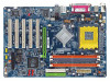
GA-7N400S DDR1 DDR2 DDR3 GA-7N400S/GA-7N400S-L Motherboard Layout KB_MS ATX_12V SOCKET A R_USB ATX COMA LPT COMB USB MIC_IN LINE_OUT LINE_IN LAN* SUR_CEN RTL8100C* SPDIF_IO CODEC F_AUDIO CD_IN AUX_IN nVIDIA nForce 2 Ultra 400 CLK_SW CPU_FAN AGP PCI1 PCI2 PCI3 IDE2 IDE1 nVIDIA nForce 2 MCP RAID SATA1 SATA0 PCI4 BIOS BAT CLR_CMOS PCI5 FDD PWR_LED IR F_USB1 F_USB2 F_PANEL SYS_FAN -L* IT8712 * Only for GA-7N400S-L. - 6 -
GA-7N400S DDR1 DDR2 DDR3 GA-7N400S/GA-7N400S-L Motherboard Layout KB_MS ATX_12V SOCKET A R_USB ATX COMA LPT COMB USB MIC_IN LINE_OUT LINE_IN LAN* SUR_CEN RTL8100C* SPDIF_IO CODEC F_AUDIO CD_IN AUX_IN nVIDIA nForce 2 Ultra 400 CLK_SW CPU_FAN AGP PCI1 PCI2 PCI3 IDE2 IDE1 nVIDIA nForce 2 MCP RAID SATA1 SATA0 PCI4 BIOS BAT CLR_CMOS PCI5 FDD PWR_LED IR F_USB1 F_USB2 F_PANEL SYS_FAN -L* IT8712 * Only for GA-7N400S-L. - 6 -

User Manual
Page 7
Block Diagram AGP 4X/8X AMD-K7 CPU CPUCLK+/-(100/133/166/200MHz) 5 PCI AGPCLK 66MHz RJ45* RTL8100C* PCI Bus 33MHz nVIDIA nForce 2 Ultra 400 nVIDIA nForce 2 MCP RAID DDR 400/333/266MHz DIMM DDR HCLK+/- (100/133/166/200MHz) NBGCLK 66 MHz 33MHz 14.318MHz 48MHz BIOS IT8712 Floppy LPT Port AC97 Link PCICLK (33MHz) CODEC 2 Serial ATA 8 USB ATA33/66/100/ Ports 133 IDE Channels 2 COM Ports 24MHz 33MHz PS/2 KB/Mouse Mic In Line In Line Out * Only for GA-7N400S-L. - 7 -
Block Diagram AGP 4X/8X AMD-K7 CPU CPUCLK+/-(100/133/166/200MHz) 5 PCI AGPCLK 66MHz RJ45* RTL8100C* PCI Bus 33MHz nVIDIA nForce 2 Ultra 400 nVIDIA nForce 2 MCP RAID DDR 400/333/266MHz DIMM DDR HCLK+/- (100/133/166/200MHz) NBGCLK 66 MHz 33MHz 14.318MHz 48MHz BIOS IT8712 Floppy LPT Port AC97 Link PCICLK (33MHz) CODEC 2 Serial ATA 8 USB ATA33/66/100/ Ports 133 IDE Channels 2 COM Ports 24MHz 33MHz PS/2 KB/Mouse Mic In Line In Line Out * Only for GA-7N400S-L. - 7 -

User Manual
Page 10
Line Out (Front Speaker Out) ; You also have to install DDR333 or DDR400 memory module(s). GA-7N400S(-L) Motherboard - 10 - For example, when using a CPU with frequencies equal to or faster than the FSB frequency of 2 FDD devices Onboard SATA &#...please set Memory Frequency under Advanced Chipset Features to Auto in BIOS Setup (refer to page 34). English 1-2 Feature Summary Motherboard Š GA-7N400S or GA-7N400S-L CPU Š Socket A for GA-7N400S-L. (Note) If you want to use DDR memory module(s) with 333Mhz FSB, you install. MIC In (Center/Subwoofer Speaker Out) &#...
Line Out (Front Speaker Out) ; You also have to install DDR333 or DDR400 memory module(s). GA-7N400S(-L) Motherboard - 10 - For example, when using a CPU with frequencies equal to or faster than the FSB frequency of 2 FDD devices Onboard SATA &#...please set Memory Frequency under Advanced Chipset Features to Auto in BIOS Setup (refer to page 34). English 1-2 Feature Summary Motherboard Š GA-7N400S or GA-7N400S-L CPU Š Socket A for GA-7N400S-L. (Note) If you want to use DDR memory module(s) with 333Mhz FSB, you install. MIC In (Center/Subwoofer Speaker Out) &#...

User Manual
Page 12
Please align this edge with the socket edge closest to the heat sink manual for heat dissipation or using extreme care when removing the heatsink. GA-7N400S(-L) Motherboard - 12 - Gently place the CPU into position making sure that either thermal tape rather than heat sink paste be properly positioned during installation. 1-4-2 Installation ...
Please align this edge with the socket edge closest to the heat sink manual for heat dissipation or using extreme care when removing the heatsink. GA-7N400S(-L) Motherboard - 12 - Gently place the CPU into position making sure that either thermal tape rather than heat sink paste be properly positioned during installation. 1-4-2 Installation ...

User Manual
Page 14
If three DDR memory modules are installed, please use memory of the same storage capacity in order to use dual channel memory. GA-7N400S / GA-7N400S-L includes 3 DIMM sockets as following: Channel A : DDR 1, DDR 2 Channel B : DDR 3 If you want to operate the Dual Channel ...memory module DDR 1 DS/SS X DS/SS DDR 2 X DS/SS DS/SS DDR 3 DS/SS DS/SS DS/SS GA-7N400S(-L) Motherboard - 14 - English Dual Channel DDR GA-7N400S / GA-7N400S-L supports the Dual Channel Technology. If two DDR memory modules are installed on the same channel. 3. The following explanations due to...
If three DDR memory modules are installed, please use memory of the same storage capacity in order to use dual channel memory. GA-7N400S / GA-7N400S-L includes 3 DIMM sockets as following: Channel A : DDR 1, DDR 2 Channel B : DDR 3 If you want to operate the Dual Channel ...memory module DDR 1 DS/SS X DS/SS DDR 2 X DS/SS DS/SS DDR 3 DS/SS DS/SS DS/SS GA-7N400S(-L) Motherboard - 14 - English Dual Channel DDR GA-7N400S / GA-7N400S-L supports the Dual Channel Technology. If two DDR memory modules are installed on the same channel. 3. The following explanations due to...

User Manual
Page 16
... your OS supports USB controller. For more information please contact your OS does not support USB controller, please contact OS ven dor for GA-7N400S-L. Parallel Port The parallel port allows connection of 10/100Mbps. If your OS or device(s) vendors. LAN Port * The provided Internet ... Before you connect your device(s) into USB connector(s), please make sure your device(s) such as USB keyboard, mouse, scanner, zip, speaker...etc. GA-7N400S(-L) Motherboard - 16 - Line In Devices like CD-ROM, walkman etc. Line Out Connect the stereo speakers or earphone to serial-based mouse or...
... your OS supports USB controller. For more information please contact your OS does not support USB controller, please contact OS ven dor for GA-7N400S-L. Parallel Port The parallel port allows connection of 10/100Mbps. If your OS or device(s) vendors. LAN Port * The provided Internet ... Before you connect your device(s) into USB connector(s), please make sure your device(s) such as USB keyboard, mouse, scanner, zip, speaker...etc. GA-7N400S(-L) Motherboard - 16 - Line In Devices like CD-ROM, walkman etc. Line Out Connect the stereo speakers or earphone to serial-based mouse or...

User Manual
Page 18
... are properly installed. Align the power connector with its proper location on /off) 15 GND 16 GND 17 GND 18 -5V 19 VCC 20 VCC GA-7N400S(-L) Motherboard - 18 - If the ATX_12V power connector is able to the CPU. Before connecting the power connector, please make sure that is used (300W or...
... are properly installed. Align the power connector with its proper location on /off) 15 GND 16 GND 17 GND 18 -5V 19 VCC 20 VCC GA-7N400S(-L) Motherboard - 18 - If the ATX_12V power connector is able to the CPU. Before connecting the power connector, please make sure that is used (300W or...

User Manual
Page 20
... 2 1 7) SATA0 / SATA1 (Serial ATA Connector) Serial ATA can then connect to work properly. 1 7 SATA1 1 7 SATA0 Pin No. 1 2 3 4 5 6 7 Definition GND TXP TXN GND RXN RXP GND GA-7N400S(-L) Motherboard - 20 - Please refer to the BIOS setting for information on settings, please refer to the computer via an IDE connector.
... 2 1 7) SATA0 / SATA1 (Serial ATA Connector) Serial ATA can then connect to work properly. 1 7 SATA1 1 7 SATA0 Pin No. 1 2 3 4 5 6 7 Definition GND TXP TXN GND RXN RXP GND GA-7N400S(-L) Motherboard - 20 - Please refer to the BIOS setting for information on settings, please refer to the computer via an IDE connector.

User Manual
Page 22
Pin 3: NC Pin 4: Data(-) Pin 1: LED anode(+) Pin 2: LED cathode(-) Open: Normal Operation Close: Reset Hardware System NC GA-7N400S(-L) Motherboard - 22 - RESRES+ NC Reset Switch IDE Hard Disk Active LED MSG (Message LED/Power/Sleep LED) PW (Power Switch) SPEAK (Speaker Connector) HD (IDE ...
Pin 3: NC Pin 4: Data(-) Pin 1: LED anode(+) Pin 2: LED cathode(-) Open: Normal Operation Close: Reset Hardware System NC GA-7N400S(-L) Motherboard - 22 - RESRES+ NC Reset Switch IDE Hard Disk Active LED MSG (Message LED/Power/Sleep LED) PW (Power Switch) SPEAK (Speaker Connector) HD (IDE ...

User Manual
Page 24
... work or even damage it. Use this feature only when your local dealer. 26 15 Pin No. 1 2 3 4 5 6 Definition VCC No Pin SPDIF SPDIFI GND GND GA-7N400S(-L) Motherboard - 24 - English 13/14) CD_IN (CD In Connector, black) / AUX_IN (AUX In Connector, white) Connect CD-ROM or DVD-ROM audio out to the...
... work or even damage it. Use this feature only when your local dealer. 26 15 Pin No. 1 2 3 4 5 6 Definition VCC No Pin SPDIF SPDIFI GND GND GA-7N400S(-L) Motherboard - 24 - English 13/14) CD_IN (CD In Connector, black) / AUX_IN (AUX In Connector, white) Connect CD-ROM or DVD-ROM audio out to the...

User Manual
Page 26
Default doesn't include the "Shunter" to its default values by this jumper. English 18) CLR_CMOS (Clear CMOS) You may clear the CMOS data to prevent from improper use this jumper. To clear CMOS, temporarily short 1-2 pin. Open: Normal 1 Short: Clear CMOS 1 GA-7N400S(-L) Motherboard - 26 -
Default doesn't include the "Shunter" to its default values by this jumper. English 18) CLR_CMOS (Clear CMOS) You may clear the CMOS data to prevent from improper use this jumper. To clear CMOS, temporarily short 1-2 pin. Open: Normal 1 Short: Clear CMOS 1 GA-7N400S(-L) Motherboard - 26 -

User Manual
Page 28
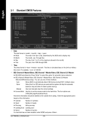
..., fan, speed. „ Load Fail-Safe Defaults Fail-Safe Defaults indicates the value of the system parameters which the system would be in safe configuration. GA-7N400S(-L) Motherboard - 28 - English The Main Menu (For example: BIOS Ver. : E17) Once you want, please press "Ctrl+F1" to accept or enter the sub-menu...
..., fan, speed. „ Load Fail-Safe Defaults Fail-Safe Defaults indicates the value of the system parameters which the system would be in safe configuration. GA-7N400S(-L) Motherboard - 28 - English The Main Menu (For example: BIOS Ver. : E17) Once you want, please press "Ctrl+F1" to accept or enter the sub-menu...
User Manual
Page 30
... Mode Use this to automatically detect IDE devices during POST. (Default value) Select this information. time clock. IDE Channel 1 Master/Slave; to Sat. Through Dec. GA-7N400S(-L) Motherboard - 30 - Cylinder Number of cylinders Head Number of heads Precomp Write precomp Landing Zone Landing zone Sector Number of three methods: Auto None Allows...
... Mode Use this to automatically detect IDE devices during POST. (Default value) Select this information. time clock. IDE Channel 1 Master/Slave; to Sat. Through Dec. GA-7N400S(-L) Motherboard - 30 - Cylinder Number of cylinders Head Number of heads Precomp Write precomp Landing Zone Landing zone Sector Number of three methods: Auto None Allows...

User Manual
Page 32
... Select your boot device priority by USB-HDD. USB-HDD Select your boot device priority by LAN. Press to move it is 360K. (Default value) GA-7N400S(-L) Motherboard - 32 - USB-FDD Select your boot device priority by ZIP. LAN Select your boot device priority by Floppy. Disabled Select your boot device priority...
... Select your boot device priority by USB-HDD. USB-HDD Select your boot device priority by LAN. Press to move it is 360K. (Default value) GA-7N400S(-L) Motherboard - 32 - USB-FDD Select your boot device priority by ZIP. LAN Select your boot device priority by Floppy. Disabled Select your boot device priority...

User Manual
Page 34
... higher risk of instability. Resulting Frequency The value depends on FSB/Memory Frequency settings. For example, when using these features may cause your system broken. GA-7N400S(-L) Motherboard - 34 - Auto Set the best memory frequency for system. (Default value) 50MHz ~ 100MHz Set AGP frequency manually. (Note) If you install. You also have...
... higher risk of instability. Resulting Frequency The value depends on FSB/Memory Frequency settings. For example, when using these features may cause your system broken. GA-7N400S(-L) Motherboard - 34 - Auto Set the best memory frequency for system. (Default value) 50MHz ~ 100MHz Set AGP frequency manually. (Note) If you install. You also have...

User Manual
Page 35
.... (Default value) Disabled Disable onboard first channel IDE port. Serial ATA Enabled Enable Serial ATA controller function. (Default value) Disabled Disable this function. * Only for GA-7N400S-L. - 35 - On-Chip Secondary PCI IDE When set at "Disabled". BIOS Setup English 2-4 Integrated Peripherals CMOS Setup Utility-Copyright (C) 1984-2004 Award Software Integrated Peripherals...
.... (Default value) Disabled Disable onboard first channel IDE port. Serial ATA Enabled Enable Serial ATA controller function. (Default value) Disabled Disable this function. * Only for GA-7N400S-L. - 35 - On-Chip Secondary PCI IDE When set at "Disabled". BIOS Setup English 2-4 Integrated Peripherals CMOS Setup Utility-Copyright (C) 1984-2004 Award Software Integrated Peripherals...

User Manual
Page 36
... RAID function. Disabled Disable this function. (Default value) IDE Channel1 Slave RAID Enabled Enable secondary slave channel IDE RAID function. Disable this function. (Default value) GA-7N400S(-L) Motherboard - 36 - Disabled Disable this function. (Default value) RAID Config CMOS Setup Utility-Copyright (C) 1984-2004 Award Software RAID Config IDE Channel0 Master RAID IDE...
... RAID function. Disabled Disable this function. (Default value) IDE Channel1 Slave RAID Enabled Enable secondary slave channel IDE RAID function. Disable this function. (Default value) GA-7N400S(-L) Motherboard - 36 - Disabled Disable this function. (Default value) RAID Config CMOS Setup Utility-Copyright (C) 1984-2004 Award Software RAID Config IDE Channel0 Master RAID IDE...

