Manual
Page 1
GA-770T-USB3 AM3 socket motherboard for AMD Phenom™ II processor/ AMD Athlon™ II processor User's Manual Rev. 1001 12ME-770TB3-1001R
GA-770T-USB3 AM3 socket motherboard for AMD Phenom™ II processor/ AMD Athlon™ II processor User's Manual Rev. 1001 12ME-770TB3-1001R

Manual
Page 2
Motherboard GA-770T-USB3 Jan. 8, 2010 Motherboard GA-770T-USB3 Jan. 8, 2010
Motherboard GA-770T-USB3 Jan. 8, 2010 Motherboard GA-770T-USB3 Jan. 8, 2010
Manual
Page 3
For product-related information, check on our website at: http://www.gigabyte.com.tw Identifying Your Motherboard Revision The revision number on your motherboard revision before updating motherboard BIOS, drivers, or when looking for technical information. Example: For instructions on our website....download the information on/from the Support&Downloads\Motherboard\Technology Guide page on how to their respective owners. Check your motherboard looks like this manual are legally registered to use of this product, GIGABYTE provides the following types of documentations: For ...
For product-related information, check on our website at: http://www.gigabyte.com.tw Identifying Your Motherboard Revision The revision number on your motherboard revision before updating motherboard BIOS, drivers, or when looking for technical information. Example: For instructions on our website....download the information on/from the Support&Downloads\Motherboard\Technology Guide page on how to their respective owners. Check your motherboard looks like this manual are legally registered to use of this product, GIGABYTE provides the following types of documentations: For ...
Manual
Page 4
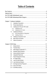
Table of Contents Box Contents...6 Optional Items...6 GA-770T-USB3 Motherboard Layout 7 GA-770T-USB3 Motherboard Block Diagram 8 Chapter 1 Hardware Installation 9 1-1 Installation Precautions 9 1-2 Product Specifications 10 1-3 Installing the CPU and CPU Cooler 13 1-3-1 Installing the CPU 13 1-3-2 Installing the CPU Cooler ...
Table of Contents Box Contents...6 Optional Items...6 GA-770T-USB3 Motherboard Layout 7 GA-770T-USB3 Motherboard Block Diagram 8 Chapter 1 Hardware Installation 9 1-1 Installation Precautions 9 1-2 Product Specifications 10 1-3 Installing the CPU and CPU Cooler 13 1-3-1 Installing the CPU 13 1-3-2 Installing the CPU Cooler ...
Manual
Page 6
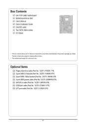
The box contents are for reference only. Box Contents GA-770T-USB3 motherboard Motherboard driver disk User's Manual Quick Installation Guide One IDE cable Two SATA 3Gb/s cables I/O Shield • The box contents above are subject to change without notice. • The motherboard image is for reference only and the actual items shall depend on the product...
The box contents are for reference only. Box Contents GA-770T-USB3 motherboard Motherboard driver disk User's Manual Quick Installation Guide One IDE cable Two SATA 3Gb/s cables I/O Shield • The box contents above are subject to change without notice. • The motherboard image is for reference only and the actual items shall depend on the product...
Manual
Page 7
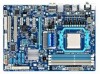
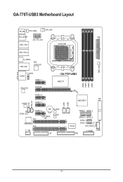
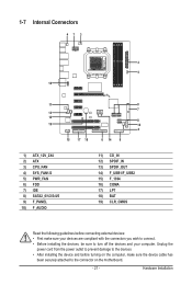
GA-770T-USB3 Motherboard Layout KB_MS SYS_FAN2 CPU_FAN RCA_SPDIF ATX ATX_12V_2X4 USB_1394_1 Socket AM3 USB_1394_2 R_USB30 USB_LAN NEC D720200F1 PWR_FAN F_AUDIO AUDIO PCIEX1_1 RTL8111D PCIEX16 GA-770T-USB3 AMD 770 DDR3_1 DDR3_2 DDR3_3 DDR3_4 PCIEX1_2 CD_IN SPDIF_IN CODEC PCIEX1_3 SPDIF_OUT PCIEX1_4 BAT M_BIOS B_BIOS CLR_CMOS PCI1 TSB43AB23 PCI2 F_1394 LPT F_USB1 F_USB2 IDE AMD SB710 SATA2_1 SATA2_3 IT8720 SATA2_0 SATA2_2 SATA2_5 SATA2_4 SYS_FAN1 F_PANEL FDD COMA - 7 -
GA-770T-USB3 Motherboard Layout KB_MS SYS_FAN2 CPU_FAN RCA_SPDIF ATX ATX_12V_2X4 USB_1394_1 Socket AM3 USB_1394_2 R_USB30 USB_LAN NEC D720200F1 PWR_FAN F_AUDIO AUDIO PCIEX1_1 RTL8111D PCIEX16 GA-770T-USB3 AMD 770 DDR3_1 DDR3_2 DDR3_3 DDR3_4 PCIEX1_2 CD_IN SPDIF_IN CODEC PCIEX1_3 SPDIF_OUT PCIEX1_4 BAT M_BIOS B_BIOS CLR_CMOS PCI1 TSB43AB23 PCI2 F_1394 LPT F_USB1 F_USB2 IDE AMD SB710 SATA2_1 SATA2_3 IT8720 SATA2_0 SATA2_2 SATA2_5 SATA2_4 SYS_FAN1 F_PANEL FDD COMA - 7 -
Manual
Page 8
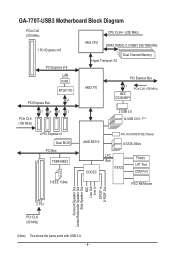
GA-770T-USB3 Motherboard Block Diagram PCIe CLK (100 MHz) 1 PCI Express x16 PCI Express x16 LAN RJ45 RTL8111D x1 PCI Express Bus CPU CLK+/- (200 MHz) AM3 CPU ...
GA-770T-USB3 Motherboard Block Diagram PCIe CLK (100 MHz) 1 PCI Express x16 PCI Express x16 LAN RJ45 RTL8111D x1 PCI Express Bus CPU CLK+/- (200 MHz) AM3 CPU ...
Manual
Page 9
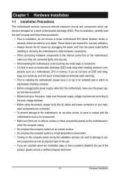
... electrostatic shielding container. • Before unplugging the power supply cable from the power outlet before installing or removing the motherboard or other hardware components. • When connecting hardware components to the internal connectors on the computer power during the ...best to wear an electrostatic discharge (ESD) wrist strap when handling electronic com- Chapter 1 Hardware Installation 1-1 Installation Precautions The motherboard contains numerous delicate electronic circuits and components which can lead to damage to system components as well as physical harm to the ...
... electrostatic shielding container. • Before unplugging the power supply cable from the power outlet before installing or removing the motherboard or other hardware components. • When connecting hardware components to the internal connectors on the computer power during the ...best to wear an electrostatic discharge (ESD) wrist strap when handling electronic com- Chapter 1 Hardware Installation 1-1 Installation Precautions The motherboard contains numerous delicate electronic circuits and components which can lead to damage to system components as well as physical harm to the ...
Manual
Page 12
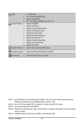
... CPU/system fan speed control function is supported will depend on the CPU/system cooler you install. (Note 5) Available functions in EasyTune may differ by motherboard model. Hardware Installation - 12 -
... CPU/system fan speed control function is supported will depend on the CPU/system cooler you install. (Note 5) Available functions in EasyTune may differ by motherboard model. Hardware Installation - 12 -
Manual
Page 13
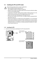
... requirements for the latest CPU support list.) • Always turn on the computer if the CPU cooler is not recommended that the motherboard supports the CPU. (Go to GIGABYTE's website for the peripherals. Hardware Installation age of the CPU may locate the notches on both sides of the CPU and alignment keys...
... requirements for the latest CPU support list.) • Always turn on the computer if the CPU cooler is not recommended that the motherboard supports the CPU. (Go to GIGABYTE's website for the peripherals. Hardware Installation age of the CPU may locate the notches on both sides of the CPU and alignment keys...
Manual
Page 14
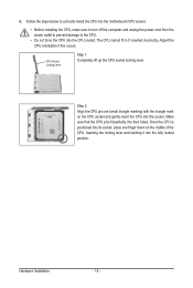
... middle of the CPU, lowering the locking lever and latching it into the socket. B. Follow the steps below to correctly install the CPU into the motherboard CPU socket. • Before installing the CPU, make sure to turn off the computer and unplug the power cord from the power outlet to prevent...
... middle of the CPU, lowering the locking lever and latching it into the socket. B. Follow the steps below to correctly install the CPU into the motherboard CPU socket. • Before installing the CPU, make sure to turn off the computer and unplug the power cord from the power outlet to prevent...
Manual
Page 15
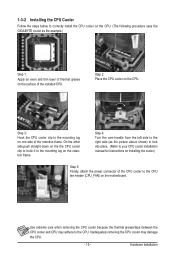
... on the CPU. 1-3-2 Installing the CPU Cooler Follow the steps below to correctly install the CPU cooler on the CPU. (The following procedure uses the GIGABYTE cooler as the picture above shows) to lock into place. (Refer to your CPU cooler installation manual for instructions on installing the cooler.) Step 5: Finally...
... on the CPU. 1-3-2 Installing the CPU Cooler Follow the steps below to correctly install the CPU cooler on the CPU. (The following procedure uses the GIGABYTE cooler as the picture above shows) to lock into place. (Refer to your CPU cooler installation manual for instructions on installing the cooler.) Step 5: Finally...

Manual
Page 16
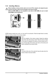
... bandwidth. The four DDR3 memory sockets are unable to insert the memory, switch the direction. 1-4-1 Dual Channel Memory Configuration This motherboard provides four DDR3 memory sockets and supports Dual Channel Technology. DS/SS DS/SS Four Modules DS/SS DS/SS DS/SS DS... damage. • Memory modules have a foolproof design. Dual Channel mode cannot be used . (Go to GIGABYTE's website for optimum performance. It is recommended that the motherboard supports the memory. Enabling Dual Channel memory mode will automatically detect the specifications and capacity of the same capacity,...
... bandwidth. The four DDR3 memory sockets are unable to insert the memory, switch the direction. 1-4-1 Dual Channel Memory Configuration This motherboard provides four DDR3 memory sockets and supports Dual Channel Technology. DS/SS DS/SS Four Modules DS/SS DS/SS DS/SS DS... damage. • Memory modules have a foolproof design. Dual Channel mode cannot be used . (Go to GIGABYTE's website for optimum performance. It is recommended that the motherboard supports the memory. Enabling Dual Channel memory mode will automatically detect the specifications and capacity of the same capacity,...
Manual
Page 17
... DIMMs are not compatible to each other or DDR DIMMs. Be sure to install DDR3 DIMMs on the socket. Place the memory module on this motherboard. Spread the retaining clips at both ends of the memory module. As indicated in the picture on the left, place your memory modules in one...
... DIMMs are not compatible to each other or DDR DIMMs. Be sure to install DDR3 DIMMs on the socket. Place the memory module on this motherboard. Spread the retaining clips at both ends of the memory module. As indicated in the picture on the left, place your memory modules in one...
Manual
Page 18
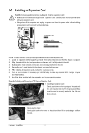
... the card until it is fully inserted into the slot. 4. If necessary, go to BIOS Setup to install an expansion card: • Make sure the motherboard supports the expansion card. Secure the card's metal bracket to correctly install your expansion card in the slot and does not rock. • Removing the...
... the card until it is fully inserted into the slot. 4. If necessary, go to BIOS Setup to install an expansion card: • Make sure the motherboard supports the expansion card. Secure the card's metal bracket to correctly install your expansion card in the slot and does not rock. • Removing the...
Manual
Page 19
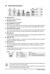
... Out Connector This connector provides digital audio out to a back panel connector, first remove the cable from your device and then remove it from the motherboard. • When removing the cable, pull it side to side to connect a PS/2 mouse. USB 2.0/1.1 Port The USB port supports the USB 2.0/1.1 specification. Use this...
... Out Connector This connector provides digital audio out to a back panel connector, first remove the cable from your device and then remove it from the motherboard. • When removing the cable, pull it side to side to connect a PS/2 mouse. USB 2.0/1.1 Port The USB port supports the USB 2.0/1.1 specification. Use this...
Manual
Page 21
... devices and your devices are compliant with the connectors you wish to connect. • Before installing the devices, be sure to the connector on the motherboard. - 21 -
... devices and your devices are compliant with the connectors you wish to connect. • Before installing the devices, be sure to the connector on the motherboard. - 21 -

Manual
Page 22
... power supply cable to an unstable or unbootable system. 4 1 8 5 ATX_12V_2X4 ATX_12V_2X4: Pin No. If a power supply is turned off and all the components on the motherboard. Before connecting the power connector, first make sure the power supply is used that can withstand high power consumption be used (500W or greater).
... power supply cable to an unstable or unbootable system. 4 1 8 5 ATX_12V_2X4 ATX_12V_2X4: Pin No. If a power supply is turned off and all the components on the motherboard. Before connecting the power connector, first make sure the power supply is used that can withstand high power consumption be used (500W or greater).
Manual
Page 23
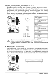
...SYS_FAN1: Pin No. Definition 1 GND 1 SYS_FAN1 2 +12V / Speed Control 3 Sense 4 Reserve 1 1 SYS_FAN2 PWR_FAN SYS_FAN2/PWR_FAN: Pin No. The motherboard supports CPU fan speed control, which requires the use of the connector and the floppy disk drive cable. Before connecting a floppy disk drive, be installed...optional floppy disk drive cable, please contact the local dealer. 33 1 34 2 - 23 - 3/4/5) CPU_FAN/SYS_FAN1/SYS_FAN2/PWR_FAN (Fan Headers) The motherboard has a 4-pin CPU fan header (CPU_FAN), a 4-pin (SYS_FAN1) and one 3-pin (SYS_ FAN2) system fan headers, and a 3-pin power...
...SYS_FAN1: Pin No. Definition 1 GND 1 SYS_FAN1 2 +12V / Speed Control 3 Sense 4 Reserve 1 1 SYS_FAN2 PWR_FAN SYS_FAN2/PWR_FAN: Pin No. The motherboard supports CPU fan speed control, which requires the use of the connector and the floppy disk drive cable. Before connecting a floppy disk drive, be installed...optional floppy disk drive cable, please contact the local dealer. 33 1 34 2 - 23 - 3/4/5) CPU_FAN/SYS_FAN1/SYS_FAN2/PWR_FAN (Fan Headers) The motherboard has a 4-pin CPU fan header (CPU_FAN), a 4-pin (SYS_FAN1) and one 3-pin (SYS_ FAN2) system fan headers, and a 3-pin power...
Manual
Page 26
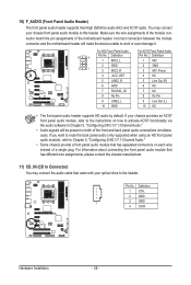
Incorrect connection between the module connector and the motherboard header will make the device unable to activate AC'97 functionality via the audio software in Chapter 5, "Configuring 2/4/5.1/7.1-Channel Audio." • Audio signals will be ... panel audio connections simultaneously. If your chassis provides an AC'97 front panel audio module, refer to the instructions on each wire instead of the motherboard header. If you want to mute the back panel audio (only supported when using an HD front panel audio module), refer to Chapter 5, "Configuring 2/4/5.1/7.1-Channel...
Incorrect connection between the module connector and the motherboard header will make the device unable to activate AC'97 functionality via the audio software in Chapter 5, "Configuring 2/4/5.1/7.1-Channel Audio." • Audio signals will be ... panel audio connections simultaneously. If your chassis provides an AC'97 front panel audio module, refer to the instructions on each wire instead of the motherboard header. If you want to mute the back panel audio (only supported when using an HD front panel audio module), refer to Chapter 5, "Configuring 2/4/5.1/7.1-Channel...


