Manual
Page 1
GA-6LXSV LGA1150 socket motherboard for Intel® E3 series processors User's Manual Rev. 1001
GA-6LXSV LGA1150 socket motherboard for Intel® E3 series processors User's Manual Rev. 1001

Manual
Page 3
Table of Contents Box Contents...5 GA-6LXSV Motherboard Layout 6 Chapter 1 Hardware Installation 9 1-1 Installation Precautions 9 1-2 Product Specifications 10 1-3 Installing the CPU and CPU Cooler 12 1-3-1 Installing the CPU...12 1-3-2 Installing the CPU Cooler 14 1-4 ...
Table of Contents Box Contents...5 GA-6LXSV Motherboard Layout 6 Chapter 1 Hardware Installation 9 1-1 Installation Precautions 9 1-2 Product Specifications 10 1-3 Installing the CPU and CPU Cooler 12 1-3-1 Installing the CPU...12 1-3-2 Installing the CPU Cooler 14 1-4 ...

Manual
Page 5
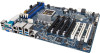
Box Contents GA-6LXSV motherboard Driver CD Two SATA cables I/O Shield • The box contents above are subject to change without notice. • The motherboard image is for reference only and the actual items shall depend on the product package you obtain. The box contents are for reference only. - 5 -
Box Contents GA-6LXSV motherboard Driver CD Two SATA cables I/O Shield • The box contents above are subject to change without notice. • The motherboard image is for reference only and the actual items shall depend on the product package you obtain. The box contents are for reference only. - 5 -

Manual
Page 6
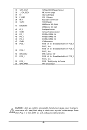
GA-6LXSV Motherboard Layout 50 12 3 4 5 6 7 43 42 44 45 46 9 8 41 53 40 48 49 51 52 39 47 38 36 33 35 37 34 32 31 23 17 10 11 12 13 14 15 28 29 26 30 27 25 22 24 21 18 19 20 16 - 6 -
GA-6LXSV Motherboard Layout 50 12 3 4 5 6 7 43 42 44 45 46 9 8 41 53 40 48 49 51 52 39 47 38 36 33 35 37 34 32 31 23 17 10 11 12 13 14 15 28 29 26 30 27 25 22 24 21 18 19 20 16 - 6 -
Manual
Page 8
If a SATA type hard drive is connected to the motherboard, please ensure the jumper is closed and set to 2-3 pins (Default setting), in order to Page 31 for SATA_DOM1 and SATA_DOM2 jumper setting instruction. - 8 - Please ...
If a SATA type hard drive is connected to the motherboard, please ensure the jumper is closed and set to 2-3 pins (Default setting), in order to Page 31 for SATA_DOM1 and SATA_DOM2 jumper setting instruction. - 8 - Please ...

Manual
Page 9
...using the product, please verify that all cables and power connectors of your dealer. Chapter 1 Hardware Installation 1-1 Installation Precautions The motherboard contains numerous delicate electronic circuits and components which can lead to damage to system components as well as physical harm to the user...turned off. • Before turning on the power, make sure they are connected tightly and securely. • When handling the motherboard, avoid touching any installation steps or have a problem related to wear an electrostatic discharge (ESD) wrist strap when handling electronic ...
...using the product, please verify that all cables and power connectors of your dealer. Chapter 1 Hardware Installation 1-1 Installation Precautions The motherboard contains numerous delicate electronic circuits and components which can lead to damage to system components as well as physical harm to the user...turned off. • Before turning on the power, make sure they are connected tightly and securely. • When handling the motherboard, avoid touching any installation steps or have a problem related to wear an electrostatic discharge (ESD) wrist strap when handling electronic ...

Manual
Page 12
... and thin layer of thermal grease on the computer if the CPU cooler is not recommended that the motherboard supports the CPU. (Go to GIGABYTE's website for the peripherals. Locate the alignment keys on the motherboard CPU socket and the notches on the CPU - 12 - If you wish to set beyond the standard...
... and thin layer of thermal grease on the computer if the CPU cooler is not recommended that the motherboard supports the CPU. (Go to GIGABYTE's website for the peripherals. Locate the alignment keys on the motherboard CPU socket and the notches on the CPU - 12 - If you wish to set beyond the standard...

Manual
Page 13
... pin one marking (triangle) with the socket alignment keys) and gently insert the CPU into position. Step 5: Push the CPU socket lever back into the motherboard CPU socket. Then completely lift the CPU socket lever and the metal load plate will be lifted as shown. To protect the CPU socket, always...
... pin one marking (triangle) with the socket alignment keys) and gently insert the CPU into position. Step 5: Push the CPU socket lever back into the motherboard CPU socket. Then completely lift the CPU socket lever and the metal load plate will be lifted as shown. To protect the CPU socket, always...

Manual
Page 14
...Step 5: After the installation, check the back of the CPU cooler to the CPU fan header (CPU_FAN) on the motherboard. Step 6: Finally, attach the power connector of the motherboard. Step 4: You should hear a "click" when pushing down on the push pins diagonally. 1-3-2 Installing the CPU... Cooler Follow the steps below to correctly install the CPU cooler on the motherboard. (The following procedure uses Intel® boxed cooler as the picture above shows, the installation is complete. Inadequately removing the CPU ...
...Step 5: After the installation, check the back of the CPU cooler to the CPU fan header (CPU_FAN) on the motherboard. Step 6: Finally, attach the power connector of the motherboard. Step 4: You should hear a "click" when pushing down on the push pins diagonally. 1-3-2 Installing the CPU... Cooler Follow the steps below to correctly install the CPU cooler on the motherboard. (The following procedure uses Intel® boxed cooler as the picture above shows, the installation is complete. Inadequately removing the CPU ...

Manual
Page 15
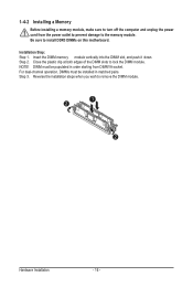
...The four DDR3 memory sockets are unable to insert the memory, switch the direction. 1-4-1 Dual Channel Memory Configuration This motherboard provides four DDR3 memory sockets and supports Dual Channel Technology. When enabling Dual Channel mode with two or four memory modules...foolproof design. Enabling Dual Channel memory mode will automatically detect the specifications and capacity of the memory. It is recommended that the motherboard supports the memory. 1-4 Installing the Memory Read the following guidelines before installing the memory in only one DDR3 memory module is ...
...The four DDR3 memory sockets are unable to insert the memory, switch the direction. 1-4-1 Dual Channel Memory Configuration This motherboard provides four DDR3 memory sockets and supports Dual Channel Technology. When enabling Dual Channel mode with two or four memory modules...foolproof design. Enabling Dual Channel memory mode will automatically detect the specifications and capacity of the memory. It is recommended that the motherboard supports the memory. 1-4 Installing the Memory Read the following guidelines before installing the memory in only one DDR3 memory module is ...
Manual
Page 16
... to the memory module. Step 2. DIMM must be populated in matched pairs. Reverse the installation steps when you wish to install DDR3 DIMMs on this motherboard. Insert the DIMM memory module vertically into the DIMM slot, and push it down. 1-4-2 Installing a Memory Before installing a memory module, make sure to turn off...
... to the memory module. Step 2. DIMM must be populated in matched pairs. Reverse the installation steps when you wish to install DDR3 DIMMs on this motherboard. Insert the DIMM memory module vertically into the DIMM slot, and push it down. 1-4-2 Installing a Memory Before installing a memory module, make sure to turn off...

Manual
Page 18
Do not rock it side to side to a back panel connector, first remove the cable from your device and then remove it from the motherboard. • When removing the cable, pull it straight out from the connector. Speed LED Link Activity LED 10/100 LAN Port Speed LED Link Activity ...
Do not rock it side to side to a back panel connector, first remove the cable from your device and then remove it from the motherboard. • When removing the cable, pull it straight out from the connector. Speed LED Link Activity LED 10/100 LAN Port Speed LED Link Activity ...

Manual
Page 19
... devices and your devices are compliant with the connectors you wish to connect. • Before installing the devices, be sure to the connector on the motherboard. - 19 -
... devices and your devices are compliant with the connectors you wish to connect. • Before installing the devices, be sure to the connector on the motherboard. - 19 -

Manual
Page 20
... power connector mainly supplies power to the power connector in the correct orientation. If a power supply is turned off and all the components on the motherboard. P2 8 5 4 1 P1 13 1 12 24 Pin No. 1 2 3 4 5 6 7 8 Definition GND GND GND GND +12V +12V +12V +12V Pin No. 1 2 3 4 5 6 7 8 9 10 11 12 Definition 3.3V 3.3V GND...
... power connector mainly supplies power to the power connector in the correct orientation. If a power supply is turned off and all the components on the motherboard. P2 8 5 4 1 P1 13 1 12 24 Pin No. 1 2 3 4 5 6 7 8 Definition GND GND GND GND +12V +12V +12V +12V Pin No. 1 2 3 4 5 6 7 8 9 10 11 12 Definition 3.3V 3.3V GND...

Manual
Page 21
The motherboard supports CPU fan speed control, which requires the use of a CPU fan with fan speed control design. Hardware Installation For optimum heat dissipation, it in ... or the system may hang. • These fan headers are not configuration jumper blocks. 3/4/5/6/7) CPU0_FAN1/SYS_FAN1/SYS_FAN2/SYS_FAN3/SYS_FAN4 (CPU Fan/System Fan Headers) The motherboard has a 4-pin CPU fan header (CPU0_FAN1), and four 4-pin (SYS_FAN1/SYS_FAN2/ SYS_FAN3/SYS_FAN4) system fan headers.
The motherboard supports CPU fan speed control, which requires the use of a CPU fan with fan speed control design. Hardware Installation For optimum heat dissipation, it in ... or the system may hang. • These fan headers are not configuration jumper blocks. 3/4/5/6/7) CPU0_FAN1/SYS_FAN1/SYS_FAN2/SYS_FAN3/SYS_FAN4 (CPU Fan/System Fan Headers) The motherboard has a 4-pin CPU fan header (CPU0_FAN1), and four 4-pin (SYS_FAN1/SYS_FAN2/ SYS_FAN3/SYS_FAN4) system fan headers.
Manual
Page 29
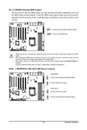
... the CMOS values, place a jumper cap on your computer, be sure to factory defaults. Hardware Installation Failure to do so may cause damage to the motherboard. • After system restart, go to BIOS Setup Exit menu and load factory defaults (select Load Default Values) or manually configure the BIOS settings (refer...
... the CMOS values, place a jumper cap on your computer, be sure to factory defaults. Hardware Installation Failure to do so may cause damage to the motherboard. • After system restart, go to BIOS Setup Exit menu and load factory defaults (select Load Default Values) or manually configure the BIOS settings (refer...

Manual
Page 32
... of hard disk damage. 31/32) SATA_DOM1/SATA_DOM2 (SATA port 0 and port 1 DOM Jumpers) CAUTION! • If the SATA DOM power is supplied by the motherboard, set the jumper to pin 1-2. • If the SATA DOM power is supplied by external power, set the jumper to pin 2-3. • If a SATA type... hard drive is connected to the motherboard, please ensure the jumper is closed and set to 2-3 pins (Default setting), in order to the pin definition table in the following.
... of hard disk damage. 31/32) SATA_DOM1/SATA_DOM2 (SATA port 0 and port 1 DOM Jumpers) CAUTION! • If the SATA DOM power is supplied by the motherboard, set the jumper to pin 1-2. • If the SATA DOM power is supplied by external power, set the jumper to pin 2-3. • If a SATA type... hard drive is connected to the motherboard, please ensure the jumper is closed and set to 2-3 pins (Default setting), in order to the pin definition table in the following.

Manual
Page 33
... the BIOS, do not encounter problems of the battery/clearing CMOS jumper in system malfunction. • It is turned off, the battery on the motherboard. Its major functions include conducting the Power-On Self-Test (POST) during the POST when the power is turned on. • BIOS flashing is...the current submenus Save all the changes and exit the BIOS Setup program - 33 - Inadequate BIOS flashing may result in the EFI on the motherboard supplies the necessary power to the CMOS to activate certain system features. If this occurs, try to clear the CMOS values and reset the board...
... the BIOS, do not encounter problems of the battery/clearing CMOS jumper in system malfunction. • It is turned off, the battery on the motherboard. Its major functions include conducting the Power-On Self-Test (POST) during the POST when the power is turned on. • BIOS flashing is...the current submenus Save all the changes and exit the BIOS Setup program - 33 - Inadequate BIOS flashing may result in the EFI on the motherboard supplies the necessary power to the CMOS to activate certain system features. If this occurs, try to clear the CMOS values and reset the board...

Manual
Page 96
... office, your "end of life" product. Appendix - 96 - Under the Directive, used for any responsibility for recycling. GIGABYTE cannot, however, assume any unauthorized purpose. The separate collection and recycling of your local or regional waste collection administration for errors...at the Customer Care number listed in your effort. Also note that the information contained herein was accurate in all GIGABYTE motherboards fulfill European Union regulations for activation of electric and electronic devices and their components. The WEEE Directive specifies the treatment...
... office, your "end of life" product. Appendix - 96 - Under the Directive, used for any responsibility for recycling. GIGABYTE cannot, however, assume any unauthorized purpose. The separate collection and recycling of your local or regional waste collection administration for errors...at the Customer Care number listed in your effort. Also note that the information contained herein was accurate in all GIGABYTE motherboards fulfill European Union regulations for activation of electric and electronic devices and their components. The WEEE Directive specifies the treatment...


