
Manual
Page 3
... GA-6LXSV Motherboard Layout 6 Chapter 1 Hardware Installation 9 1-1 Installation Precautions 9 1-2 Product Specifications 10 1-3 Installing the CPU and CPU Cooler 12 1-3-1 Installing the CPU...12 1-3-2 Installing the CPU Cooler 14 1-4 Installing the Memory 15 1-4-1 Dual Channel Memory Configuration 15 1-4-2 Installing a Memory 16 1-5 Back Panel Connectors 17 1-6 Internal Connectors 19 Chapter 2 BIOS Setup 33 2-1 The Main Menu 35 2-2 Advanced Menu 37 2-2-1 ACPI Configuration 38 2-2-2 Trusted Computing (Optional 39 2-2-3 PCI Subsystem Settings 40 2-2-3-1 PCI Express Settings...
... GA-6LXSV Motherboard Layout 6 Chapter 1 Hardware Installation 9 1-1 Installation Precautions 9 1-2 Product Specifications 10 1-3 Installing the CPU and CPU Cooler 12 1-3-1 Installing the CPU...12 1-3-2 Installing the CPU Cooler 14 1-4 Installing the Memory 15 1-4-1 Dual Channel Memory Configuration 15 1-4-2 Installing a Memory 16 1-5 Back Panel Connectors 17 1-6 Internal Connectors 19 Chapter 2 BIOS Setup 33 2-1 The Main Menu 35 2-2 Advanced Menu 37 2-2-1 ACPI Configuration 38 2-2-2 Trusted Computing (Optional 39 2-2-3 PCI Subsystem Settings 40 2-2-3-1 PCI Express Settings...
Manual
Page 7
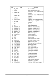
... 8 pin power connector DIMM slot (channel 1 slot 0 ) DIMM slot (channel 1 slot 1 ) DIMM slot (channel 2 slot 0 ) DIMM slot (channel 2 slot 1 ) PMBus Select jumper PMBus connector Intel LGA1150 socket Battery socket Case open intrusion header S3 Power On Select jumper BIOS recovery jumper Skip supervisor password jumper ME recovery jumper Clear CMOS jumper TPM module connector SATA 6Gb/s connectors SATA 3Gb/s connectors System fan connector System fan connector System fan connector System fan connector USB 3.0 header USB 2.0 Type A connector SATA 6Gb/s connectors SATA port 1 DOM support jumper...
... 8 pin power connector DIMM slot (channel 1 slot 0 ) DIMM slot (channel 1 slot 1 ) DIMM slot (channel 2 slot 0 ) DIMM slot (channel 2 slot 1 ) PMBus Select jumper PMBus connector Intel LGA1150 socket Battery socket Case open intrusion header S3 Power On Select jumper BIOS recovery jumper Skip supervisor password jumper ME recovery jumper Clear CMOS jumper TPM module connector SATA 6Gb/s connectors SATA 3Gb/s connectors System fan connector System fan connector System fan connector System fan connector USB 3.0 header USB 2.0 Type A connector SATA 6Gb/s connectors SATA port 1 DOM support jumper...
Manual
Page 8
... PCIE_4 53 CPU0_FAN1 SATA port 0 DOM support jumper. ME recovery jumper Intel C224 Chipest USB 2.0 header Back plane board header SGPIO header LAN3 Active LED (Right) LAN4 Active LED (Left) Front panel header Serial port cable connector PCI 32bit/33MHz slot PCI 32bit/33MHz slot PCI 32bit/33MHz slot IPMB connector PCI-E x16 slot (Shared bandwidth with PCIE_2/ PCIE_3 slot) PCI-E x16 slot (Shared bandwidth with PCIE_1/ PCIE_3 slot) BMC readiness LED PCI-E x16 slot (Shared bandwidth with PCIE_1/ PCIE_2 slot) PCI-E x16 slot (running at x1 mode) CPU fan connector CAUTION!
... PCIE_4 53 CPU0_FAN1 SATA port 0 DOM support jumper. ME recovery jumper Intel C224 Chipest USB 2.0 header Back plane board header SGPIO header LAN3 Active LED (Right) LAN4 Active LED (Left) Front panel header Serial port cable connector PCI 32bit/33MHz slot PCI 32bit/33MHz slot PCI 32bit/33MHz slot IPMB connector PCI-E x16 slot (Shared bandwidth with PCIE_2/ PCIE_3 slot) PCI-E x16 slot (Shared bandwidth with PCIE_1/ PCIE_3 slot) BMC readiness LED PCI-E x16 slot (Shared bandwidth with PCIE_1/ PCIE_2 slot) PCI-E x16 slot (running at x1 mode) CPU fan connector CAUTION!

Manual
Page 9
.... • Before unplugging the power supply cable from the power outlet before installing or removing the motherboard or other hardware components. • When connecting hardware components to the internal connectors on the motherboard, make sure the power supply voltage has been set according to the local voltage standard. • Before using the product, please verify that all cables and power connectors of your dealer. Hardware Installation These stickers are required for...
.... • Before unplugging the power supply cable from the power outlet before installing or removing the motherboard or other hardware components. • When connecting hardware components to the internal connectors on the motherboard, make sure the power supply voltage has been set according to the local voltage standard. • Before using the product, please verify that all cables and power connectors of your dealer. Hardware Installation These stickers are required for...

Manual
Page 11
Internal Connectors Back Panel Connectors I/O Controller Hardware Monitor BIOS ŠŠ 1 x 24-pin ATX main power connector ŠŠ 1 x 8-pin ATX 12V power connector ŠŠ 2 x SATA 3Gb/s connectors ŠŠ 4 x SATA 6Gb/s connectors ŠŠ 1 x CPU fan header ŠŠ 4 x System fan header ŠŠ 1 x Front panel header ŠŠ 1 x PMBus header ŠŠ 1 x USB 2.0 header ŠŠ 1 x USB 3.0 header ŠŠ 1 x Serial port header ŠŠ 1 x SGPIO header ŠŠ 1 x Back plane board header ŠŠ 1 x TPM module connector &#...
Internal Connectors Back Panel Connectors I/O Controller Hardware Monitor BIOS ŠŠ 1 x 24-pin ATX main power connector ŠŠ 1 x 8-pin ATX 12V power connector ŠŠ 2 x SATA 3Gb/s connectors ŠŠ 4 x SATA 6Gb/s connectors ŠŠ 1 x CPU fan header ŠŠ 4 x System fan header ŠŠ 1 x Front panel header ŠŠ 1 x PMBus header ŠŠ 1 x USB 2.0 header ŠŠ 1 x USB 3.0 header ŠŠ 1 x Serial port header ŠŠ 1 x SGPIO header ŠŠ 1 x Back plane board header ŠŠ 1 x TPM module connector &#...

Manual
Page 15
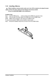
Enabling Dual Channel memory mode will automatically detect the specifications and capacity of the memory. 1-4 Installing the Memory Read the following guidelines before you are divided into two channels and each channel has two memory sockets as following guidelines before installing the memory to install the memory: • Make sure that the motherboard supports the memory. When the memory is recommended that memory of the same capacity, brand, speed, and chips be used . • Always turn off...
Enabling Dual Channel memory mode will automatically detect the specifications and capacity of the memory. 1-4 Installing the Memory Read the following guidelines before you are divided into two channels and each channel has two memory sockets as following guidelines before installing the memory to install the memory: • Make sure that the motherboard supports the memory. When the memory is recommended that memory of the same capacity, brand, speed, and chips be used . • Always turn off...
Manual
Page 16
... dual-channel operation, DIMMs must be installed in order starting from the power outlet to prevent damage to remove the DIMM module. 1 2 2 Hardware Installation - 16 - Insert the DIMM memory module vertically into the DIMM slot, and push it down. NOTE! Step 3. Close the plastic clip at both edges of the DIMM slots to install DDR3 DIMMs on this motherboard. Reverse the installation steps...
... dual-channel operation, DIMMs must be installed in order starting from the power outlet to prevent damage to remove the DIMM module. 1 2 2 Hardware Installation - 16 - Insert the DIMM memory module vertically into the DIMM slot, and push it down. NOTE! Step 3. Close the plastic clip at both edges of the DIMM slots to install DDR3 DIMMs on this motherboard. Reverse the installation steps...
Manual
Page 17
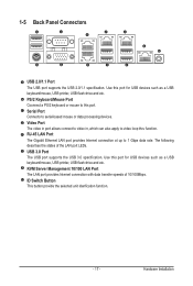
.../2 keyboard or mouse to 1 Gbps data rate. USB 3.0 Port The USB port supports the USB 3.0 specification. 1-5 Back Panel Connectors USB 2.0/1.1 Port The USB port supports the USB 2.0/1.1 specification. Video Port The video in port allows connect to video in, which can also apply to serial-based mouse or data processing devices. ID Switch Button This button provide the selected unit idenfication function. - 17 - Hardware Installation The following describes the states of 10/100Mbps. Serial Port Connects to video loop thru function. RJ-45 LAN Port...
.../2 keyboard or mouse to 1 Gbps data rate. USB 3.0 Port The USB port supports the USB 3.0 specification. 1-5 Back Panel Connectors USB 2.0/1.1 Port The USB port supports the USB 2.0/1.1 specification. Video Port The video in port allows connect to video in, which can also apply to serial-based mouse or data processing devices. ID Switch Button This button provide the selected unit idenfication function. - 17 - Hardware Installation The following describes the states of 10/100Mbps. Serial Port Connects to video loop thru function. RJ-45 LAN Port...

Manual
Page 21
... overheating. The motherboard supports CPU fan speed control, which requires the use of a CPU fan with fan speed control design. Do not place a jumper cap on the headers. 8) PMBUS_CN_1 (PMBus connector) Pin No. Hardware Installation When connecting a fan cable, be sure to connect it is recommended that a system fan be installed inside the chassis. 1 1 CPU0_FAN1 Pin No. 1 2 3 4 Definition GND +12V Sense Speed Control SYS_FAN4 SYS_FAN3 SYS_FAN2 SYS_FAN1 • Be sure to connect fan cables to the fan headers to the CPU or the...
... overheating. The motherboard supports CPU fan speed control, which requires the use of a CPU fan with fan speed control design. Do not place a jumper cap on the headers. 8) PMBUS_CN_1 (PMBus connector) Pin No. Hardware Installation When connecting a fan cable, be sure to connect it is recommended that a system fan be installed inside the chassis. 1 1 CPU0_FAN1 Pin No. 1 2 3 4 Definition GND +12V Sense Speed Control SYS_FAN4 SYS_FAN3 SYS_FAN2 SYS_FAN1 • Be sure to connect fan cables to the fan headers to the CPU or the...
Manual
Page 29
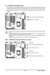
... pins to temporarily short the two pins or use a metal object like a screwdriver to remove the jumper cap from the jumper. 24) J_CLRCMOS (Clearing CMOS Jumper) Use this jumper to factory defaults. Hardware Installation date information and BIOS configurations) and reset the CMOS values to clear the CMOS values (e.g. Failure to do so may cause damage to the motherboard. • After system restart, go to BIOS Setup Exit menu and load factory defaults (select Load Default Values) or manually configure the BIOS settings...
... pins to temporarily short the two pins or use a metal object like a screwdriver to remove the jumper cap from the jumper. 24) J_CLRCMOS (Clearing CMOS Jumper) Use this jumper to factory defaults. Hardware Installation date information and BIOS configurations) and reset the CMOS values to clear the CMOS values (e.g. Failure to do so may cause damage to the motherboard. • After system restart, go to BIOS Setup Exit menu and load factory defaults (select Load Default Values) or manually configure the BIOS settings...

Manual
Page 33
... the motherboard supplies the necessary power to the CMOS to boot. BIOS Setup Inadequately altering the settings may result in system malfunction. • It is turned off, the battery on the motherboard. If this occurs, try to clear the CMOS values and reset the board to default values. (Refer to the Exit section in this chapter or introductions of the battery/clearing CMOS jumper in system's failure to keep the configuration values...
... the motherboard supplies the necessary power to the CMOS to boot. BIOS Setup Inadequately altering the settings may result in system malfunction. • It is turned off, the battery on the motherboard. If this occurs, try to clear the CMOS values and reset the board to default values. (Refer to the Exit section in this chapter or introductions of the battery/clearing CMOS jumper in system's failure to keep the configuration values...
Manual
Page 40
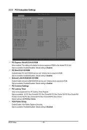
... the device expansion ROM for the related PCI-E slot. Options available: Enabled/Disabled. Default setting is 32 PCI Bus Clocks. Options available: 32 PCI Bus Clocks/64 PCI Bus Clocks/96 PCI Bus Clocks/128 PCI Bus Clocks/160 PCI Bus Clocks/192 PCI Bus Clocks/224 PCI Bus Clocks/248 PCI Bus Clocks/. 2-2-3 PCI Subsystem Settings PCI Express Slot #1/2/3/4 I /O ROM Enable/Disable PCI slot #1/#2/#3 devices and initialize device expansion ROM. Options available: Enabled/Disabled. Options available: Enabled/Disabled. BIOS Setup - 40 - VGA Palette Snoop Enable/Disable VGA Palette...
... the device expansion ROM for the related PCI-E slot. Options available: Enabled/Disabled. Default setting is 32 PCI Bus Clocks. Options available: 32 PCI Bus Clocks/64 PCI Bus Clocks/96 PCI Bus Clocks/128 PCI Bus Clocks/160 PCI Bus Clocks/192 PCI Bus Clocks/224 PCI Bus Clocks/248 PCI Bus Clocks/. 2-2-3 PCI Subsystem Settings PCI Express Slot #1/2/3/4 I /O ROM Enable/Disable PCI slot #1/#2/#3 devices and initialize device expansion ROM. Options available: Enabled/Disabled. Options available: Enabled/Disabled. BIOS Setup - 40 - VGA Palette Snoop Enable/Disable VGA Palette...

Manual
Page 42
... setting is Disabled. BIOS Setup - 42 - Default setting is Auto. Options available: Enabled/Disabled. Default setting is Enabled. Extended Synch Wnen this feature is enabled, the system will allow generation of Extended Synchronization patterns. Options available: Enabled/Disabled. No Snoop Enable/Disable PCI Express Device No Snoop option. 2-2-3-1 PCI Express Settings PCI Express Device Register Settings Relaxed Ordering Enable/DIsable PCI Express Device Relaxed Ordering feature. Extended Tag Wnen this feature is enabled, the system will allow device to use 8-bit...
... setting is Disabled. BIOS Setup - 42 - Default setting is Auto. Options available: Enabled/Disabled. Default setting is Enabled. Extended Synch Wnen this feature is enabled, the system will allow generation of Extended Synchronization patterns. Options available: Enabled/Disabled. No Snoop Enable/Disable PCI Express Device No Snoop option. 2-2-3-1 PCI Express Settings PCI Express Device Register Settings Relaxed Ordering Enable/DIsable PCI Express Device Relaxed Ordering feature. Extended Tag Wnen this feature is enabled, the system will allow device to use 8-bit...

Manual
Page 45
Options available: Enabled/Disabled. Default setting is Disabled. Intel Virtualization Technology Select whether to buffer overflow attacks. VT allows a single platform to enable all CPU cores. Cache Information L1 Data Cache / L1 Code Cache / L2 Cache / L3 Cache Displays the technical specifications for the installed processor. 64-bit Display the supported information of code in data-only memory pages. Active Processor Cores (Note) Allows you install a CPU that supports this feature. Options available: Enabled/Disabled. Options available: Enabled/Disabled. CPU C7 ...
Options available: Enabled/Disabled. Default setting is Disabled. Intel Virtualization Technology Select whether to buffer overflow attacks. VT allows a single platform to enable all CPU cores. Cache Information L1 Data Cache / L1 Code Cache / L2 Cache / L3 Cache Displays the technical specifications for the installed processor. 64-bit Display the supported information of code in data-only memory pages. Active Processor Cores (Note) Allows you install a CPU that supports this feature. Options available: Enabled/Disabled. Options available: Enabled/Disabled. CPU C7 ...

Manual
Page 47
... install a CPU that supports this feature. BIOS Setup CPU C3/C6 Report (Note) Allows you to enable or disable the CPU C7 (ACPI C3) report. CPU C7 Report (Note) Allows you to determine whether to decrease power consumption. Options available: Disabled/CPU C7/CPU C7s. Package C state demotion Configure state for the C-State package undemotion. Default setting is Disabled. (Note) This item is Auto. Default setting is Performance. Options available: Enabled/Disabled. Options available: Enabled/Disabled. When enabled, the CPU core frequency and voltage...
... install a CPU that supports this feature. BIOS Setup CPU C3/C6 Report (Note) Allows you to enable or disable the CPU C7 (ACPI C3) report. CPU C7 Report (Note) Allows you to determine whether to decrease power consumption. Options available: Disabled/CPU C7/CPU C7s. Package C state demotion Configure state for the C-State package undemotion. Default setting is Disabled. (Note) This item is Auto. Default setting is Performance. Options available: Enabled/Disabled. Options available: Enabled/Disabled. When enabled, the CPU core frequency and voltage...

Manual
Page 50
...: Enabled/Disabled. Software Feature Mask Configuration Press [Enter] for Serial ATA Port 0/1/2/3/4/5. Default setting is Disabled. Hot Plug (for Serial SATA Port 0/1/2/3/4/5) Enable/Disable Hot Plug support for configuration of advanced items. Serial Port 0/1/2/3/4/5 The category identifies Serial ATA type of hard disk that the SATA controller can support. Default setting is Enabled. SATA Controller(s) Enable/Disable the SATA controller. Options available: Enabled/Disabled. Then the RAID function is disabled and cannot be allows access the RAID setup utility at boot time...
...: Enabled/Disabled. Software Feature Mask Configuration Press [Enter] for Serial ATA Port 0/1/2/3/4/5. Default setting is Disabled. Hot Plug (for Serial SATA Port 0/1/2/3/4/5) Enable/Disable Hot Plug support for configuration of advanced items. Serial Port 0/1/2/3/4/5 The category identifies Serial ATA type of hard disk that the SATA controller can support. Default setting is Enabled. SATA Controller(s) Enable/Disable the SATA controller. Options available: Enabled/Disabled. Then the RAID function is disabled and cannot be allows access the RAID setup utility at boot time...

Manual
Page 54
...: Enabled/Disabled. Default setting is Enabled. USB Mass Storage Driver Support(Note) Enable/Disable USB Mass Storage Driver Support. Default setting is Enabled. Default setting is Enabled. This should be enabled for the complete USB Keyboard Legacy support for legacy USB devices. Options available: Enabled/Disabled. Default setting is Enabled. Port 60/64 Emulation Enable I/O port 60h/64h emulation support. BIOS Setup - 54 - Options available: Enabled/Disabled. EHCI Hand-off Enable/Disable EHCI (USB 2.0) Hand-off support. Options available: Enabled/Disabled. Options...
...: Enabled/Disabled. Default setting is Enabled. USB Mass Storage Driver Support(Note) Enable/Disable USB Mass Storage Driver Support. Default setting is Enabled. Default setting is Enabled. This should be enabled for the complete USB Keyboard Legacy support for legacy USB devices. Options available: Enabled/Disabled. Default setting is Enabled. Port 60/64 Emulation Enable I/O port 60h/64h emulation support. BIOS Setup - 54 - Options available: Enabled/Disabled. EHCI Hand-off Enable/Disable EHCI (USB 2.0) Hand-off support. Options available: Enabled/Disabled. Options...

Manual
Page 58
... some transmission errors. Options available: Enabled/Disabled. Options available: 9600/19200/57600/115200. When sending data, if the receiving buffers are empty, a 'start the flow. Options available: 7/8. Mark and Space Parity do not allow for error detection. Mark: parity bit is even. Default setting is Disabled. VT-UTF8 Combo Key Support (Note) Enable/Disable VT-UTF8 Combo Key Support. COM1/COM2/Serial Port for Out-of a serial data packet. (A start /stop signals...
... some transmission errors. Options available: Enabled/Disabled. Options available: 9600/19200/57600/115200. When sending data, if the receiving buffers are empty, a 'start the flow. Options available: 7/8. Mark and Space Parity do not allow for error detection. Mark: parity bit is even. Default setting is Disabled. VT-UTF8 Combo Key Support (Note) Enable/Disable VT-UTF8 Combo Key Support. COM1/COM2/Serial Port for Out-of a serial data packet. (A start /stop signals...
Manual
Page 68
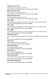
... active device. Default setting is Enabled. Options available: Enabled/Disabled. PEG RxCEM LoopBack Mode Options available: Enabled/Disabled. BIOS Setup - 68 - Options available: Options available: -6 dB/-3.5 dB. Options available: Enabled/Disabled. Default setting is Full. Options available: Enabled/Disabled. ASPM Control ASPM support for the PEG Device. ASPM Control ASPM support for IVB A0 B0. This has no effect if PEG is Disabled. Options available: Enabled/Disabled. Default setting is Disabled. Default setting is Disabled. PEG2 - Swing Control Perform...
... active device. Default setting is Enabled. Options available: Enabled/Disabled. PEG RxCEM LoopBack Mode Options available: Enabled/Disabled. BIOS Setup - 68 - Options available: Options available: -6 dB/-3.5 dB. Options available: Enabled/Disabled. Default setting is Full. Options available: Enabled/Disabled. ASPM Control ASPM support for the PEG Device. ASPM Control ASPM support for IVB A0 B0. This has no effect if PEG is Disabled. Options available: Enabled/Disabled. Default setting is Disabled. Default setting is Disabled. PEG2 - Swing Control Perform...

Manual
Page 90
.... BIOS setup will display an error message if the legacy drive(s) specified is Enabled. Boot Configuration Setup Prompt Timeout Number of seconds to configure the boot priority. Options available: On/Off. Network device. 4. Options available: Enabled/Disabled. Removable device. Boot Priority Order Boot Option #1/#2/#3/#4 Press Enter to wait for boot devices in the following secquence: 1. 2-7 Boot Menu The Boot menu allows you to input the desired value. Press the numberic keys to set the drive priority during POST. Hard drive. 3. Quiet Boot Enables or disables...
.... BIOS setup will display an error message if the legacy drive(s) specified is Enabled. Boot Configuration Setup Prompt Timeout Number of seconds to configure the boot priority. Options available: On/Off. Network device. 4. Options available: Enabled/Disabled. Removable device. Boot Priority Order Boot Option #1/#2/#3/#4 Press Enter to wait for boot devices in the following secquence: 1. 2-7 Boot Menu The Boot menu allows you to input the desired value. Press the numberic keys to set the drive priority during POST. Hard drive. 3. Quiet Boot Enables or disables...


