
User Manual
Page 2
Motherboard G1.Sniper M3 Mar. 15, 2012 Motherboard G1.Sniper M3 Mar. 15, 2012
Motherboard G1.Sniper M3 Mar. 15, 2012 Motherboard G1.Sniper M3 Mar. 15, 2012
User Manual
Page 3
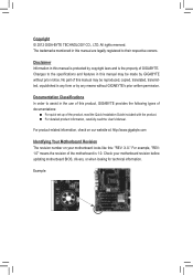
... the property of this manual is protected by any means without prior notice. Check your motherboard looks like this product, GIGABYTE provides the following types of documentations: „„ For quick set-up of this : "REV: X.X." Example: All ...GIGA-BYTE TECHNOLOGY CO., LTD. For product-related information, check on our website at: http://www.gigabyte.com Identifying Your Motherboard Revision The revision number on your motherboard revision before updating motherboard BIOS, drivers, or when looking for technical information. The trademarks mentioned in this manual may be...
... the property of this manual is protected by any means without prior notice. Check your motherboard looks like this product, GIGABYTE provides the following types of documentations: „„ For quick set-up of this : "REV: X.X." Example: All ...GIGA-BYTE TECHNOLOGY CO., LTD. For product-related information, check on our website at: http://www.gigabyte.com Identifying Your Motherboard Revision The revision number on your motherboard revision before updating motherboard BIOS, drivers, or when looking for technical information. The trademarks mentioned in this manual may be...
User Manual
Page 4
Table of Contents Box Contents...6 Optional Items...6 G1.Sniper M3 Motherboard Layout 7 G1.Sniper M3 Motherboard Block Diagram 8 Chapter 1 Hardware Installation 9 1-1 Installation Precautions 9 1-2 Product Specifications 10 1-3 Installing the CPU and CPU Cooler 13 1-3-1 Installing the CPU 13 1-3-2 Installing the CPU Cooler ...
Table of Contents Box Contents...6 Optional Items...6 G1.Sniper M3 Motherboard Layout 7 G1.Sniper M3 Motherboard Block Diagram 8 Chapter 1 Hardware Installation 9 1-1 Installation Precautions 9 1-2 Product Specifications 10 1-3 Installing the CPU and CPU Cooler 13 1-3-1 Installing the CPU 13 1-3-2 Installing the CPU Cooler ...
User Manual
Page 6
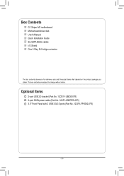
Optional Items †† 2-port USB 2.0 bracket (Part No. 12CR1-1UB030-5*R) †† 2-port SATA power cable (Part No. 12CF1-2SERPW-0*R) †† 3.5" Front Panel with 2 USB 3.0/2.0 ports (Part No. 12CR1-FPX582-0*R) - 6 - Box Contents 55 G1.Sniper M3 motherboard 55 Motherboard driver disk 55 User's Manual 55 Quick Installation Guide 55 Six SATA 6Gb/s cables 55 I/O Shield 55 One 2-Way SLI bridge connector The box contents above are subject to change without notice. The box contents are for reference only and the actual items shall depend on the product package you obtain.
Optional Items †† 2-port USB 2.0 bracket (Part No. 12CR1-1UB030-5*R) †† 2-port SATA power cable (Part No. 12CF1-2SERPW-0*R) †† 3.5" Front Panel with 2 USB 3.0/2.0 ports (Part No. 12CR1-FPX582-0*R) - 6 - Box Contents 55 G1.Sniper M3 motherboard 55 Motherboard driver disk 55 User's Manual 55 Quick Installation Guide 55 Six SATA 6Gb/s cables 55 I/O Shield 55 One 2-Way SLI bridge connector The box contents above are subject to change without notice. The box contents are for reference only and the actual items shall depend on the product package you obtain.
User Manual
Page 7
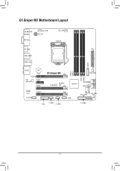
G1.Sniper M3 Motherboard Layout KB_MB_USB DVI VGA SYS_FAN3 ATX_12V CPU_FAN LGA1155 DP_HDMI ATX USB_ESATA USB30_LAN F_USB30 AUDIO BAT PCIEX16 Intel GbE LAN PCIEX1 PCIEX4 G1.Sniper M3 B_BIOS M_BIOS DDR3_4 DDR3_2 SYS_FAN2 DDR3_3 DDR3_1 Intel® Z77 SATA3 1 0 SATA2 3 2 iTE Super I/O CODEC PCIEX8 F_AUDIO TPM F_USB3 F_USB2 F_USB1 CLR_CMOS SYS_FAN1 SATA2 4 F_PANEL - 7 -
G1.Sniper M3 Motherboard Layout KB_MB_USB DVI VGA SYS_FAN3 ATX_12V CPU_FAN LGA1155 DP_HDMI ATX USB_ESATA USB30_LAN F_USB30 AUDIO BAT PCIEX16 Intel GbE LAN PCIEX1 PCIEX4 G1.Sniper M3 B_BIOS M_BIOS DDR3_4 DDR3_2 SYS_FAN2 DDR3_3 DDR3_1 Intel® Z77 SATA3 1 0 SATA2 3 2 iTE Super I/O CODEC PCIEX8 F_AUDIO TPM F_USB3 F_USB2 F_USB1 CLR_CMOS SYS_FAN1 SATA2 4 F_PANEL - 7 -
User Manual
Page 8
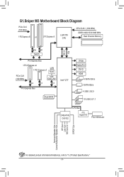
G1.Sniper M3 Motherboard Block Diagram PCIe CLK (100 MHz) 1 PCI Express x16 or 2 PCI Express x8 LGA1155 CPU CPU CLK+/- (100 MHz) DDR3 1600/1333/1066 MHz Dual ...
G1.Sniper M3 Motherboard Block Diagram PCIe CLK (100 MHz) 1 PCI Express x16 or 2 PCI Express x8 LGA1155 CPU CPU CLK+/- (100 MHz) DDR3 1600/1333/1066 MHz Dual ...
User Manual
Page 9
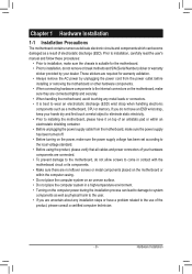
...remove the AC power by your hands dry and first touch a metal object to eliminate static electricity. •• Prior to installing the motherboard, please have it on top of an antistatic pad or within an electrostatic shielding container. •• Before unplugging the power supply cable from... manual and follow these procedures: •• Prior to installation, make sure they are no leftover screws or metal components placed on the motherboard or within the computer casing. •• Do not place the computer system on an uneven surface. •• Do not place the...
...remove the AC power by your hands dry and first touch a metal object to eliminate static electricity. •• Prior to installing the motherboard, please have it on top of an antistatic pad or within an electrostatic shielding container. •• Before unplugging the power supply cable from... manual and follow these procedures: •• Prior to installation, make sure they are no leftover screws or metal components placed on the motherboard or within the computer casing. •• Do not place the computer system on an uneven surface. •• Do not place the...
User Manual
Page 12
... for Auto Green Support for ON/OFF Charge Support for Q-Share Support for 3D Power Support for EasyTune * Available functions in EasyTune may differ by motherboard model.
... for Auto Green Support for ON/OFF Charge Support for Q-Share Support for 3D Power Support for EasyTune * Available functions in EasyTune may differ by motherboard model.
User Manual
Page 13
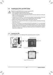
... installing the CPU to your hardware specifications including the CPU, graphics card, memory, hard drive, etc. 1-3-1 Installing the CPU A. Locate the alignment keys on the motherboard CPU socket and the notches on the computer if the CPU cooler is not recommended that the...
... installing the CPU to your hardware specifications including the CPU, graphics card, memory, hard drive, etc. 1-3-1 Installing the CPU A. Locate the alignment keys on the motherboard CPU socket and the notches on the computer if the CPU cooler is not recommended that the...

User Manual
Page 14
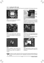
... completely lift the CPU socket lever and the metal load plate will be lifted as shown. Step 5: Push the CPU socket lever back into the motherboard CPU socket. B. When replacing the load plate, make sure to turn off the computer and unplug the power cord from the socket with the pin...
... completely lift the CPU socket lever and the metal load plate will be lifted as shown. Step 5: Push the CPU socket lever back into the motherboard CPU socket. B. When replacing the load plate, make sure to turn off the computer and unplug the power cord from the socket with the pin...
User Manual
Page 15
... of the CPU cooler to the CPU fan header (CPU_FAN) on installing the cooler.) Step 5: After the installation, check the back of the motherboard. Hardware Installation If the push pin is inserted as the example cooler.) Direction of the Arrow Sign on the Male Push Pin Male Push Pin... push pin along the direction of the installed CPU. 1-3-2 Installing the CPU Cooler Follow the steps below to correctly install the CPU cooler on the motherboard. (The following procedure uses Intel® boxed cooler as the picture above shows, the installation is to install.) Step 3: Place the cooler atop ...
... of the CPU cooler to the CPU fan header (CPU_FAN) on installing the cooler.) Step 5: After the installation, check the back of the motherboard. Hardware Installation If the push pin is inserted as the example cooler.) Direction of the Arrow Sign on the Male Push Pin Male Push Pin... push pin along the direction of the installed CPU. 1-3-2 Installing the CPU Cooler Follow the steps below to correctly install the CPU cooler on the motherboard. (The following procedure uses Intel® boxed cooler as the picture above shows, the installation is to install.) Step 3: Place the cooler atop ...
User Manual
Page 16
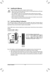
... is installed. 2. The four DDR3 memory sockets are unable to insert the memory, switch the direction. 1-4-1 Dual Channel Memory Configuration This motherboard provides four DDR3 memory sockets and supports Dual Channel Technology. Dual Channel mode cannot be enabled if only one direction. When enabling Dual Channel...install the memory: •• Make sure that memory of the same capacity, brand, speed, and chips be used . (Go to GIGABYTE's website for the latest supported memory speeds and memory modules.) •• Always turn off the computer and unplug the power cord from the...
... is installed. 2. The four DDR3 memory sockets are unable to insert the memory, switch the direction. 1-4-1 Dual Channel Memory Configuration This motherboard provides four DDR3 memory sockets and supports Dual Channel Technology. Dual Channel mode cannot be enabled if only one direction. When enabling Dual Channel...install the memory: •• Make sure that memory of the same capacity, brand, speed, and chips be used . (Go to GIGABYTE's website for the latest supported memory speeds and memory modules.) •• Always turn off the computer and unplug the power cord from the...
User Manual
Page 17
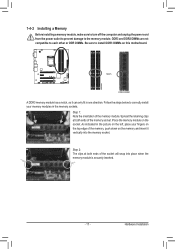
... DIMM A DDR3 memory module has a notch, so it vertically into place when the memory module is securely inserted. - 17 - Place the memory module on this motherboard. Hardware Installation
... DIMM A DDR3 memory module has a notch, so it vertically into place when the memory module is securely inserted. - 17 - Place the memory module on this motherboard. Hardware Installation
User Manual
Page 18
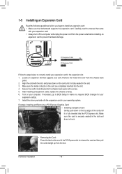
... panel with the expansion card in the expansion slot. 1. If necessary, go to BIOS Setup to install an expansion card: •• Make sure the motherboard supports the expansion card. Example: Installing and Removing a PCI Express Graphics Card: •• Installing a Graphics Card: Gently push down on your operating system. Hardware...
... panel with the expansion card in the expansion slot. 1. If necessary, go to BIOS Setup to install an expansion card: •• Make sure the motherboard supports the expansion card. Example: Installing and Removing a PCI Express Graphics Card: •• Installing a Graphics Card: Gently push down on your operating system. Hardware...
User Manual
Page 19
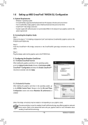
... is selected. Step 2: Insert the CrossFireX(Note)/SLI bridge connectors in the operating system, go to the NVIDIA Control Panel. C-2. Hardware Installation A CrossFireX/SLI-supported motherboard with sufficient power is recommended (Refer to Performance\AMD CrossFireX™ Configuration and ensure the Enable CrossFireX™ check box is enabled. (Note) The bridge...
... is selected. Step 2: Insert the CrossFireX(Note)/SLI bridge connectors in the operating system, go to the NVIDIA Control Panel. C-2. Hardware Installation A CrossFireX/SLI-supported motherboard with sufficient power is recommended (Refer to Performance\AMD CrossFireX™ Configuration and ensure the Enable CrossFireX™ check box is enabled. (Note) The bridge...
User Manual
Page 20
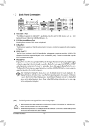
... adapter. •• When removing the cable connected to a back panel connector, first remove the cable from your device and then remove it from the motherboard. •• When removing the cable, pull it side to side to connect a PS/2 mouse or keyboard.
... adapter. •• When removing the cable connected to a back panel connector, first remove the cable from your device and then remove it from the motherboard. •• When removing the cable, pull it side to side to connect a PS/2 mouse or keyboard.
User Manual
Page 21
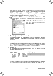
... states of transmitting uncompressed audio/video signals. Refer to the default playback device. Hardware Installation You can use this port for the Onboard Graphics: This motherboard provides four video output ports: D-Sub, DVI-D, HDMI, and DisplayPort. It also supports up to 192KHz/24bit 8-channel LPCM audio output. After installing the HDMI...
... states of transmitting uncompressed audio/video signals. Refer to the default playback device. Hardware Installation You can use this port for the Onboard Graphics: This motherboard provides four video output ports: D-Sub, DVI-D, HDMI, and DisplayPort. It also supports up to 192KHz/24bit 8-channel LPCM audio output. After installing the HDMI...

User Manual
Page 23
... sure your devices are compliant with the connectors you wish to connect. •• Before installing the devices, be sure to the connector on the motherboard. - 23 -
... sure your devices are compliant with the connectors you wish to connect. •• Before installing the devices, be sure to the connector on the motherboard. - 23 -

User Manual
Page 24
... used that can supply enough stable power to all devices are properly installed. If a power supply is turned off and all the components on the motherboard. Before connecting the power connector, first make sure the power supply is used (500W or greater). The power connector possesses a foolproof design. The 12V power...
... used that can supply enough stable power to all devices are properly installed. If a power supply is turned off and all the components on the motherboard. Before connecting the power connector, first make sure the power supply is used (500W or greater). The power connector possesses a foolproof design. The 12V power...
User Manual
Page 25
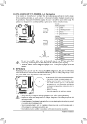
... one. Replace the battery when the battery voltage drops to prevent your computer and unplug the power cord. 2. Do not place a jumper cap on this motherboard are not configuration jumper blocks. Overheating may be installed inside the chassis. Turn off . Gently remove the battery from overheating. Definition 1 GND 2 +12V 3 Sense 4 Speed...
... one. Replace the battery when the battery voltage drops to prevent your computer and unplug the power cord. 2. Do not place a jumper cap on this motherboard are not configuration jumper blocks. Overheating may be installed inside the chassis. Turn off . Gently remove the battery from overheating. Definition 1 GND 2 +12V 3 Sense 4 Speed...


