User Guide
Page 1
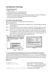
... primary store partition) MBR format: DISKPART>list disk DISKPART>select disk X DISKPART>create partition primary (Lists the disks and information about them) (Selects a disk. All motherboard drivers correctly installed B. System Requirements 1. Windows 7 with size larger than the total system memory 3. IDE mode not supported 5. For example, to set 8 GB, enter 8192...
... primary store partition) MBR format: DISKPART>list disk DISKPART>select disk X DISKPART>create partition primary (Lists the disks and information about them) (Selects a disk. All motherboard drivers correctly installed B. System Requirements 1. Windows 7 with size larger than the total system memory 3. IDE mode not supported 5. For example, to set 8 GB, enter 8192...
User Guide
Page 2
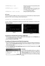
... exact volume number) (Change the partition type) (Figure 3) GPT format: Follow the commands for MBR format. The Timer slider in the operating system, insert the motherboard driver disk, go to Application Software\Install Application Software, and select Intel Rapid Start Technology to the SSD after completing the commands above. Instructions: The...
... exact volume number) (Change the partition type) (Figure 3) GPT format: Follow the commands for MBR format. The Timer slider in the operating system, insert the motherboard driver disk, go to Application Software\Install Application Software, and select Intel Rapid Start Technology to the SSD after completing the commands above. Instructions: The...
User Guide
Page 3
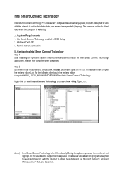
... your computer when completed. Normal network connection B. Restart your system is suspended (sleeping). Configuring Intel Smart Connect Technology Step 1: After installing the operating system and motherboard drivers, install the Intel Smart Connect Technology application. Intel Smart Connect Technology Intel Smart Connect Technology (Note) allows user's computer to automatically update programs designed...
... your computer when completed. Normal network connection B. Restart your system is suspended (sleeping). Configuring Intel Smart Connect Technology Step 1: After installing the operating system and motherboard drivers, install the Intel Smart Connect Technology application. Intel Smart Connect Technology Intel Smart Connect Technology (Note) allows user's computer to automatically update programs designed...
User Guide
Page 5
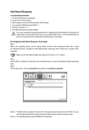
... 64 GB can still be lost once you back up the hard disk before configuring the Smart Response Technology, all motherboard drivers, including the Intel Rapid Storage Technology driver. An Intel Chipset-based motherboard 2. It is recommended that you enable RAID mode. j k (Note 1) The SSD works as a cache of... the motherboard driver disk to open the Intel Rapid Storage Technology utility. Intel Smart Response A. A conventional SATA disk and an SSD (Note 1) 5. B. System Requirements 1. Step ...
... 64 GB can still be lost once you back up the hard disk before configuring the Smart Response Technology, all motherboard drivers, including the Intel Rapid Storage Technology driver. An Intel Chipset-based motherboard 2. It is recommended that you enable RAID mode. j k (Note 1) The SSD works as a cache of... the motherboard driver disk to open the Intel Rapid Storage Technology utility. Intel Smart Response A. A conventional SATA disk and an SSD (Note 1) 5. B. System Requirements 1. Step ...

Manual
Page 2
Motherboard G1.Sniper 3 Mar. 20, 2012 Motherboard G1.Sniper 3 Mar. 20, 2012
Motherboard G1.Sniper 3 Mar. 20, 2012 Motherboard G1.Sniper 3 Mar. 20, 2012
Manual
Page 3
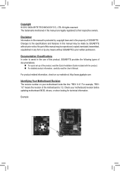
...All rights reserved. For product-related information, check on our website at: http://www.gigabyte.com Identifying Your Motherboard Revision The revision number on your motherboard revision before updating motherboard BIOS, drivers, or when looking for technical information. Example: Changes to their respective... read the User's Manual. Check your motherboard looks like this manual may be made by GIGABYTE without GIGABYTE's prior written permission. Documentation Classifications In order to assist in the use of this product, GIGABYTE provides the following types of documentations: „...
...All rights reserved. For product-related information, check on our website at: http://www.gigabyte.com Identifying Your Motherboard Revision The revision number on your motherboard revision before updating motherboard BIOS, drivers, or when looking for technical information. Example: Changes to their respective... read the User's Manual. Check your motherboard looks like this manual may be made by GIGABYTE without GIGABYTE's prior written permission. Documentation Classifications In order to assist in the use of this product, GIGABYTE provides the following types of documentations: „...
Manual
Page 4
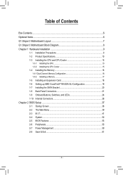
Table of Contents Box Contents...6 Optional Items...6 G1.Sniper 3 Motherboard Layout 7 G1.Sniper 3 Motherboard Block Diagram 8 Chapter 1 Hardware Installation 9 1-1 Installation Precautions 9 1-2 Product Specifications 10 1-3 Installing the CPU and CPU Cooler 13 1-3-1 Installing the CPU 13 1-3-2 Installing the CPU Cooler ...
Table of Contents Box Contents...6 Optional Items...6 G1.Sniper 3 Motherboard Layout 7 G1.Sniper 3 Motherboard Block Diagram 8 Chapter 1 Hardware Installation 9 1-1 Installation Precautions 9 1-2 Product Specifications 10 1-3 Installing the CPU and CPU Cooler 13 1-3-1 Installing the CPU 13 1-3-2 Installing the CPU Cooler ...
Manual
Page 6
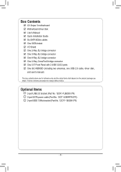
User's Manual ;; Six SATA 6Gb/s cables ;; Motherboard driver disk ;; One GC-WB300D (including two antennas, one USB 2.0 cable, driver disk, and user's manual) The box contents above are subject to change without ... 2-port USB 2.0 bracket (Part No. 12CR1-1UB030-5*R) 2-port SATA power cable (Part No. 12CF1-2SERPW-0*R) 2-port IEEE 1394a bracket (Part No. 12CF1-1IE008-0*R) - 6 - Box Contents ;; G1.Sniper 3 motherboard ;; One 2-Way SLI bridge connector ;; One 4-Way SLI bridge connector ;; The box contents are for reference only and the actual items shall depend on the...
User's Manual ;; Six SATA 6Gb/s cables ;; Motherboard driver disk ;; One GC-WB300D (including two antennas, one USB 2.0 cable, driver disk, and user's manual) The box contents above are subject to change without ... 2-port USB 2.0 bracket (Part No. 12CR1-1UB030-5*R) 2-port SATA power cable (Part No. 12CF1-2SERPW-0*R) 2-port IEEE 1394a bracket (Part No. 12CF1-1IE008-0*R) - 6 - Box Contents ;; G1.Sniper 3 motherboard ;; One 2-Way SLI bridge connector ;; One 4-Way SLI bridge connector ;; The box contents are for reference only and the actual items shall depend on the...
Manual
Page 7
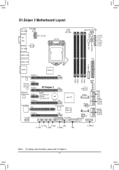
G1.Sniper 3 Motherboard Layout SYS_FAN3 KB_USB3 ATX_12V_2X4 DVI VGA VIA VL810 DP_HDMI USB30_LAN2 USB30_LAN1 LGA1155 CPU_FAN SYS_FAN2 Debug LED (Note) PW_SW CMOS_SW RST_SW VCORE CPUVTT VSA CPUPLL DDRVTT VDIMM PCHIO ATX F_USB30_2 AUDIO PEX8747 PCIEX16_1 Intel® GbE LAN Qualcomm Atheros Killer E2201 LAN PCIEX_1 PCIEX8_1 G1.Sniper 3 CREATIVE B_BIOS CA0132 Chip PCIEX1_2 BBIOS_LED M_BIOS BAT...
G1.Sniper 3 Motherboard Layout SYS_FAN3 KB_USB3 ATX_12V_2X4 DVI VGA VIA VL810 DP_HDMI USB30_LAN2 USB30_LAN1 LGA1155 CPU_FAN SYS_FAN2 Debug LED (Note) PW_SW CMOS_SW RST_SW VCORE CPUVTT VSA CPUPLL DDRVTT VDIMM PCHIO ATX F_USB30_2 AUDIO PEX8747 PCIEX16_1 Intel® GbE LAN Qualcomm Atheros Killer E2201 LAN PCIEX_1 PCIEX8_1 G1.Sniper 3 CREATIVE B_BIOS CA0132 Chip PCIEX1_2 BBIOS_LED M_BIOS BAT...
Manual
Page 8
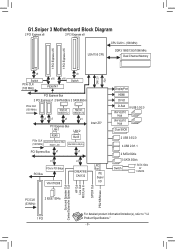
G1.Sniper 3 Motherboard Block Diagram 2 PCI Express x8 2 PCI Express x8 LGA1155 CPU CPU CLK+/- (100 MHz) DDR3 1600/1333/1066 MHz Dual Channel Memory 1 PCI Express x16 1 ...
G1.Sniper 3 Motherboard Block Diagram 2 PCI Express x8 2 PCI Express x8 LGA1155 CPU CPU CLK+/- (100 MHz) DDR3 1600/1333/1066 MHz Dual Channel Memory 1 PCI Express x16 1 ...
Manual
Page 9
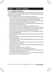
... power connectors of your hands dry and first touch a metal object to eliminate static electricity. •• Prior to installing the motherboard, please have a problem related to the use of electrostatic discharge (ESD). Hardware Installation If you do not have an ESD wrist .... •• When connecting hardware components to the internal connectors on the computer power during the installation process can become damaged as a motherboard, CPU or memory. Prior to installation, carefully read the user's manual and follow these procedures: •• Prior to wear an ...
... power connectors of your hands dry and first touch a metal object to eliminate static electricity. •• Prior to installing the motherboard, please have a problem related to the use of electrostatic discharge (ESD). Hardware Installation If you do not have an ESD wrist .... •• When connecting hardware components to the internal connectors on the computer power during the installation process can become damaged as a motherboard, CPU or memory. Prior to installation, carefully read the user's manual and follow these procedures: •• Prior to wear an ...
Manual
Page 12
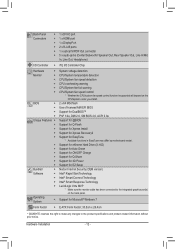
... Charge Support for Q-Share Support for 3D Power Support for EasyTune * Available functions in EasyTune may differ by motherboard model. Support for Microsoft® Windows 7 E-ATX Form Factor; 30.5cm x 26.4cm * GIGABYTE reserves the right to make any changes to the integrated graphics port(s) on the CPU/system cooler you install...
... Charge Support for Q-Share Support for 3D Power Support for EasyTune * Available functions in EasyTune may differ by motherboard model. Support for Microsoft® Windows 7 E-ATX Form Factor; 30.5cm x 26.4cm * GIGABYTE reserves the right to make any changes to the integrated graphics port(s) on the CPU/system cooler you install...
Manual
Page 13
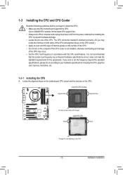
...surface of the CPU. •• Do not turn on the computer if the CPU cooler is not recommended that the motherboard supports the CPU. (Go to GIGABYTE's website for the latest CPU support list.) •• Always turn off the computer and unplug the power cord from the...according to your hardware specifications including the CPU, graphics card, memory, hard drive, etc. 1-3-1 Installing the CPU A. Locate the alignment keys on the motherboard CPU socket and the notches on the CPU - 13 - 1-3 Installing the CPU and CPU Cooler Read the following guidelines before installing the CPU to...
...surface of the CPU. •• Do not turn on the computer if the CPU cooler is not recommended that the motherboard supports the CPU. (Go to GIGABYTE's website for the latest CPU support list.) •• Always turn off the computer and unplug the power cord from the...according to your hardware specifications including the CPU, graphics card, memory, hard drive, etc. 1-3-1 Installing the CPU A. Locate the alignment keys on the motherboard CPU socket and the notches on the CPU - 13 - 1-3 Installing the CPU and CPU Cooler Read the following guidelines before installing the CPU to...
Manual
Page 14
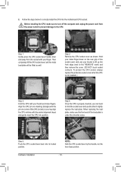
... cord from the socket with the socket alignment keys) and gently insert the CPU into position. Step 5: Push the CPU socket lever back into the motherboard CPU socket. NOTE: Hold the CPU socket lever by the handle, not the lever base portion. Step 2: Remove the CPU socket cover as well. Align...
... cord from the socket with the socket alignment keys) and gently insert the CPU into position. Step 5: Push the CPU socket lever back into the motherboard CPU socket. NOTE: Hold the CPU socket lever by the handle, not the lever base portion. Step 2: Remove the CPU socket cover as well. Align...
Manual
Page 15
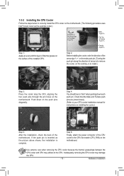
...instructions on installing the cooler.) Step 5: After the installation, check the back of the CPU cooler to the CPU fan header (CPU_FAN) on the motherboard. Inadequately removing the CPU cooler may adhere to the CPU. Push down each push pin. Step 4: You should hear a "click" when pushing ..., the installation is to install.) Step 3: Place the cooler atop the CPU, aligning the four push pins through the pin holes on the motherboard. Step 2: Before installing the cooler, note the direction of the arrow sign on the push pins diagonally. Use extreme care when removing the...
...instructions on installing the cooler.) Step 5: After the installation, check the back of the CPU cooler to the CPU fan header (CPU_FAN) on the motherboard. Inadequately removing the CPU cooler may adhere to the CPU. Push down each push pin. Step 4: You should hear a "click" when pushing ..., the installation is to install.) Step 3: Place the cooler atop the CPU, aligning the four push pins through the pin holes on the motherboard. Step 2: Before installing the cooler, note the direction of the arrow sign on the push pins diagonally. Use extreme care when removing the...
Manual
Page 16
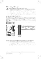
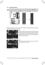
... DDR3_2 DDR3_3 Two Modules - - For optimum performance, when enabling Dual Channel mode with two or four memory modules, it is recommended that the motherboard supports the memory. DS/SS - - Dual Channel mode cannot be enabled if only one direction. It is recommended that you install them in...Dual Channel mode with two memory modules, we recommend that memory of the same capacity, brand, speed, and chips be used . (Go to GIGABYTE's website for the latest supported memory speeds and memory modules.) • Always turn off the computer and unplug the power cord from the power outlet...
... DDR3_2 DDR3_3 Two Modules - - For optimum performance, when enabling Dual Channel mode with two or four memory modules, it is recommended that the motherboard supports the memory. DS/SS - - Dual Channel mode cannot be enabled if only one direction. It is recommended that you install them in...Dual Channel mode with two memory modules, we recommend that memory of the same capacity, brand, speed, and chips be used . (Go to GIGABYTE's website for the latest supported memory speeds and memory modules.) • Always turn off the computer and unplug the power cord from the power outlet...
Manual
Page 17
... the power cord from the power outlet to prevent damage to install DDR3 DIMMs on the socket. Hardware Installation Place the memory module on this motherboard. Step 1: Note the orientation of the memory socket. DDR3 and DDR2 DIMMs are not compatible to each other or DDR DIMMs. Be sure to the...
... the power cord from the power outlet to prevent damage to install DDR3 DIMMs on the socket. Hardware Installation Place the memory module on this motherboard. Step 1: Note the orientation of the memory socket. DDR3 and DDR2 DIMMs are not compatible to each other or DDR DIMMs. Be sure to the...
Manual
Page 18
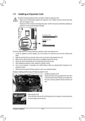
... that came with a screw. 5. Remove the metal slot cover from the power outlet before you begin to install an expansion card: • Make sure the motherboard supports the expansion card. Make sure the metal contacts on the top edge of the PCI Express slot to release the card and then pull...
... that came with a screw. 5. Remove the metal slot cover from the power outlet before you begin to install an expansion card: • Make sure the motherboard supports the expansion card. Make sure the metal contacts on the top edge of the PCI Express slot to release the card and then pull...
Manual
Page 19
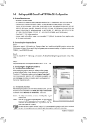
... on your graphics cards for enabling CrossFireX/SLI technology may be needed or not depending on the number of your graphics cards. A CrossFireX/SLI-supported motherboard with two/three/four PCI Express x16 slots and correct driver -- Browse to ensure system stability.
... on your graphics cards for enabling CrossFireX/SLI technology may be needed or not depending on the number of your graphics cards. A CrossFireX/SLI-supported motherboard with two/three/four PCI Express x16 slots and correct driver -- Browse to ensure system stability.
Manual
Page 20
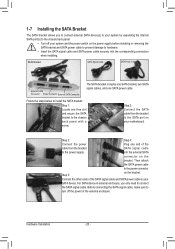
... into the external SATA connector on the power supply before installing or removing the SATA bracket and SATA power cable to prevent damage to your motherboard. 1-7 Installing the SATA Bracket The SATA bracket allows you only need to the chassis back panel with a screw. Connect the other ends of the external...
... into the external SATA connector on the power supply before installing or removing the SATA bracket and SATA power cable to prevent damage to your motherboard. 1-7 Installing the SATA Bracket The SATA bracket allows you only need to the chassis back panel with a screw. Connect the other ends of the external...


