
Manual
Page 1
G1.Assassin LGA1366 socket motherboard for Intel® Core™ i7 processor family User's Manual Rev. 1002 12ME-G1ASSAS-1002R
G1.Assassin LGA1366 socket motherboard for Intel® Core™ i7 processor family User's Manual Rev. 1002 12ME-G1ASSAS-1002R

Manual
Page 2
Motherboard G1.Assassin Jan. 12, 2011 Motherboard G1.Assassin Jan. 12, 2011
Motherboard G1.Assassin Jan. 12, 2011 Motherboard G1.Assassin Jan. 12, 2011

Manual
Page 3
...owners. For product-related information, check on our website at: http://www.gigabyte.com Identifying Your Motherboard Revision The revision number on your motherboard revision before updating motherboard BIOS, drivers, or when looking for technical information. All rights reserved. ...product information, carefully read the User's Manual. Check your motherboard looks like this manual may be made by GIGABYTE without GIGABYTE's prior written permission. The trademarks mentioned in this product, GIGABYTE provides the following types of documentations: For quick ...
...owners. For product-related information, check on our website at: http://www.gigabyte.com Identifying Your Motherboard Revision The revision number on your motherboard revision before updating motherboard BIOS, drivers, or when looking for technical information. All rights reserved. ...product information, carefully read the User's Manual. Check your motherboard looks like this manual may be made by GIGABYTE without GIGABYTE's prior written permission. The trademarks mentioned in this product, GIGABYTE provides the following types of documentations: For quick ...
Manual
Page 4
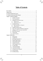
Table of Contents Box Contents...6 Optional Items...6 G1.Assassin Motherboard Layout 7 G1.Assassin Motherboard Block Diagram 8 Chapter 1 Hardware Installation 9 1-1 Installation Precautions 9 1-2 Product Specifications 10 1-3 Installing the CPU and CPU Cooler 13 1-3-1 Installing the CPU 13 1-3-2 Installing the CPU Cooler ...
Table of Contents Box Contents...6 Optional Items...6 G1.Assassin Motherboard Layout 7 G1.Assassin Motherboard Block Diagram 8 Chapter 1 Hardware Installation 9 1-1 Installation Precautions 9 1-2 Product Specifications 10 1-3 Installing the CPU and CPU Cooler 13 1-3-1 Installing the CPU 13 1-3-2 Installing the CPU Cooler ...

Manual
Page 6
Box Contents G1.Assassin motherboard Motherboard driver disk User's Manual Quick Installation Guide Four SATA cables I/O Shield 5.25" Front Access Control Panel with 2 USB 3.0/2.0 ports, 1 Power eSATA port, and 1 Quick Boost ... bridge connector One 3-Way SLI bridge connector One 2-Way CrossFireX bridge connector • The box contents above are subject to change without notice. • The motherboard image is for reference only and the actual items shall depend on the product package you obtain. The box contents are for reference only. Optional...
Box Contents G1.Assassin motherboard Motherboard driver disk User's Manual Quick Installation Guide Four SATA cables I/O Shield 5.25" Front Access Control Panel with 2 USB 3.0/2.0 ports, 1 Power eSATA port, and 1 Quick Boost ... bridge connector One 3-Way SLI bridge connector One 2-Way CrossFireX bridge connector • The box contents above are subject to change without notice. • The motherboard image is for reference only and the actual items shall depend on the product package you obtain. The box contents are for reference only. Optional...
Manual
Page 7
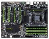
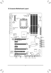
... DDR3_3 DDR3_6 DDR3_5 Bigfoot Killer E2100 Intel® X58 HP_PWR LAN_LED PCIE_12V_1 PCIEX16_1 NB Voltage L1/2/3 Renesas D720200 PCIEX1_1 SYSTEM1 Temp. LED PHASE LED ATX G1.Assassin DDR Voltage LED SYSTEM3 Temp. G1.Assassin Motherboard Layout KB_MS ATX_12V_2X SYS_FAN COAXIAL R_USB SYSTEM2 Temp.
... DDR3_3 DDR3_6 DDR3_5 Bigfoot Killer E2100 Intel® X58 HP_PWR LAN_LED PCIE_12V_1 PCIEX16_1 NB Voltage L1/2/3 Renesas D720200 PCIEX1_1 SYSTEM1 Temp. LED PHASE LED ATX G1.Assassin DDR Voltage LED SYSTEM3 Temp. G1.Assassin Motherboard Layout KB_MS ATX_12V_2X SYS_FAN COAXIAL R_USB SYSTEM2 Temp.

Manual
Page 8
G1.Assassin Motherboard Block Diagram 2 PCI Express x8 2 PCI Express x8 LGA1366 CPU CPU CLK+/- (133 MHz) DDR3 2200/1333/1066/800 MHz Dual/3 Channel Memory 1 PCI Express ...
G1.Assassin Motherboard Block Diagram 2 PCI Express x8 2 PCI Express x8 LGA1366 CPU CPU CLK+/- (133 MHz) DDR3 2200/1333/1066/800 MHz Dual/3 Channel Memory 1 PCI Express ...

Manual
Page 9
... the product, please verify that all cables and power connectors of your dealer. ponents such as a motherboard, CPU or memory. Chapter 1 Hardware Installation 1-1 Installation Precautions The motherboard contains numerous delicate electronic circuits and components which can lead to damage to system components as well as ...ESD wrist strap, keep your hands dry and first touch a metal object to eliminate static electricity. • Prior to installing the motherboard, please have it on top of an antistatic pad or within the computer casing. • Do not place the computer system on...
... the product, please verify that all cables and power connectors of your dealer. ponents such as a motherboard, CPU or memory. Chapter 1 Hardware Installation 1-1 Installation Precautions The motherboard contains numerous delicate electronic circuits and components which can lead to damage to system components as well as ...ESD wrist strap, keep your hands dry and first touch a metal object to eliminate static electricity. • Prior to installing the motherboard, please have it on top of an antistatic pad or within the computer casing. • Do not place the computer system on...

Manual
Page 12
... ŠŠ Support for Xpress Install ŠŠ Support for Xpress Recovery2 ŠŠ Support for EasyTune * Available functions in EasyTune may differ by motherboard model. ŠŠ Support for Dynamic Energy Saver™ 2 ŠŠ Support for Smart 6™ ŠŠ Support for Auto Green Š...138;Š Support for Microsoft® Windows® 7/Vista/XP Form Factor ŠŠ XL-ATX Form Factor; 34.5cm x 26.3cm * GIGABYTE reserves the right to make any changes to the product specifications and product-related information without prior notice.
... ŠŠ Support for Xpress Install ŠŠ Support for Xpress Recovery2 ŠŠ Support for EasyTune * Available functions in EasyTune may differ by motherboard model. ŠŠ Support for Dynamic Energy Saver™ 2 ŠŠ Support for Smart 6™ ŠŠ Support for Auto Green Š...138;Š Support for Microsoft® Windows® 7/Vista/XP Form Factor ŠŠ XL-ATX Form Factor; 34.5cm x 26.3cm * GIGABYTE reserves the right to make any changes to the product specifications and product-related information without prior notice.

Manual
Page 13
... host frequency in accordance with the CPU specifications. Locate the alignment keys on the motherboard CPU socket and the notches on the CPU Notch Notch - 13 - It is not recommended that the motherboard supports the CPU. (Go to GIGABYTE's website for the peripherals. LGA1366 CPU Socket Pin One Corner of the CPU. •...
... host frequency in accordance with the CPU specifications. Locate the alignment keys on the motherboard CPU socket and the notches on the CPU Notch Notch - 13 - It is not recommended that the motherboard supports the CPU. (Go to GIGABYTE's website for the peripherals. LGA1366 CPU Socket Pin One Corner of the CPU. •...

Manual
Page 14
... - 14 - Step 5: Once the CPU is not installed.) Step 4: Hold the CPU with your thumb and index finger to correctly install the CPU into the motherboard CPU socket. B. Step 2: Lift the metal load plate from the socket with the socket alignment keys) and gently insert the CPU into its locked position...
... - 14 - Step 5: Once the CPU is not installed.) Step 4: Hold the CPU with your thumb and index finger to correctly install the CPU into the motherboard CPU socket. B. Step 2: Lift the metal load plate from the socket with the socket alignment keys) and gently insert the CPU into its locked position...

Manual
Page 15
... the CPU. - 15 - Check that the Male and Female push pins are joined closely. (Refer to your CPU cooler installation manual for instructions on the motherboard. Push down each push pin. 1-3-2 Installing the CPU Cooler Follow the steps below to correctly install the CPU cooler on the... above shows, the installation is to install.) Step 3: Place the cooler atop the CPU, aligning the four push pins through the pin holes on the motherboard. Hardware Installation Direction of the Arrow Sign on the Male Push Pin Male Push Pin The Top of Female Push Pin Female Push Pin Step...
... the CPU. - 15 - Check that the Male and Female push pins are joined closely. (Refer to your CPU cooler installation manual for instructions on the motherboard. Push down each push pin. 1-3-2 Installing the CPU Cooler Follow the steps below to correctly install the CPU cooler on the... above shows, the installation is to install.) Step 3: Place the cooler atop the CPU, aligning the four push pins through the pin holes on the motherboard. Hardware Installation Direction of the Arrow Sign on the Male Push Pin Male Push Pin The Top of Female Push Pin Female Push Pin Step...

Manual
Page 16
... same capacity, brand, speed, and chips be used. If you begin to insert the memory, switch the direction. 1-4-1 Dual/3 Channel Memory Configuration This motherboard provides six DDR3 memory sockets and supports Dual/3 Channel Technology. Four Modules DS/SS DS/SS DS/SS DS/SS - - - - 3 Channel Memory...installed, the BIOS will automatically detect the specifications and capacity of the same capacity, brand, speed, and chips be used . (Go to GIGABYTE's website for the latest supported memory speeds and momery moudles.) • Always turn off the computer and unplug the power cord from the...
... same capacity, brand, speed, and chips be used. If you begin to insert the memory, switch the direction. 1-4-1 Dual/3 Channel Memory Configuration This motherboard provides six DDR3 memory sockets and supports Dual/3 Channel Technology. Four Modules DS/SS DS/SS DS/SS DS/SS - - - - 3 Channel Memory...installed, the BIOS will automatically detect the specifications and capacity of the same capacity, brand, speed, and chips be used . (Go to GIGABYTE's website for the latest supported memory speeds and momery moudles.) • Always turn off the computer and unplug the power cord from the...

Manual
Page 17
... in the memory sockets. Step 2: The clips at both ends of the memory module. As indicated in one direction. Place the memory module on this motherboard. 1-4-2 Installing a Memory Before installing a memory module, make sure to turn off the computer and unplug the power cord from the power outlet to prevent damage...
... in the memory sockets. Step 2: The clips at both ends of the memory module. As indicated in one direction. Place the memory module on this motherboard. 1-4-2 Installing a Memory Before installing a memory module, make sure to turn off the computer and unplug the power cord from the power outlet to prevent damage...
Manual
Page 18
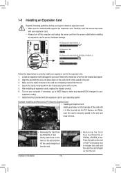
... Card: • Installing a Graphics Card: Gently push down on your card. Secure the card's metal bracket to install an expansion card: • Make sure the motherboard supports the expansion card. Turn on the card until it is fully inserted into the slot. 4. After installing all expansion cards, replace the chassis cover...
... Card: • Installing a Graphics Card: Gently push down on your card. Secure the card's metal bracket to install an expansion card: • Make sure the motherboard supports the expansion card. Turn on the card until it is fully inserted into the slot. 4. After installing all expansion cards, replace the chassis cover...
Manual
Page 19
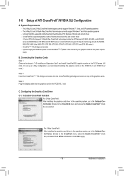
System Requirements - A CrossFireX/SLI-supported motherboard with sufficient power is selected. To Enable CrossFireX Function For 2-Way CrossFireX: After installing the graphics card driver in the operating system, go to the ...
System Requirements - A CrossFireX/SLI-supported motherboard with sufficient power is selected. To Enable CrossFireX Function For 2-Way CrossFireX: After installing the graphics card driver in the operating system, go to the ...
Manual
Page 21
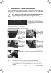
...to overclock the CPU and the button will light green. - 21 - Step 2: Connect the Quick Boost button's cable to the OC_BUTTON header on the motherboard. (Note 2) Step 3: Step 4: Connect the USB Connect the Power 3.0/2.0 ports' cable to eSATA power cable the F_USB30_1 or F_ to the defaults, ...press the button again and the button will light red. Hardware Installation To return to Pin 1, 3, 5, and 7 USB30_2 header on the motherboard. Connect the Power eSATA signal cable to a free SATA port on the power supply before installing or removing the Front Access Control Panel and ...
...to overclock the CPU and the button will light green. - 21 - Step 2: Connect the Quick Boost button's cable to the OC_BUTTON header on the motherboard. (Note 2) Step 3: Step 4: Connect the USB Connect the Power 3.0/2.0 ports' cable to eSATA power cable the F_USB30_1 or F_ to the defaults, ...press the button again and the button will light red. Hardware Installation To return to Pin 1, 3, 5, and 7 USB30_2 header on the motherboard. Connect the Power eSATA signal cable to a free SATA port on the power supply before installing or removing the Front Access Control Panel and ...

Manual
Page 22
.... Do not rock it straight out from the connector. Hardware Installation - 22 - Use this feature, ensure that your device and then remove it from the motherboard. • When removing the cable, pull it side to side to prevent an electrical short inside the cable connector. Line Out Jack (Green) The line...
.... Do not rock it straight out from the connector. Hardware Installation - 22 - Use this feature, ensure that your device and then remove it from the motherboard. • When removing the cable, pull it side to side to prevent an electrical short inside the cable connector. Line Out Jack (Green) The line...

Manual
Page 24
... when the temperature is illuminated when the temperature exceeds 80oC. The LEDs are off when the temperature is below 60oC; 1-9 Onboard LEDs Overvoltage LEDs This motherboard contains 4 sets of overvoltage LEDs which level the CPU is overclocked. LED Off: Normal condition F_LED1~F_LED5: Blue Temperature Indicator LEDs The temperature indicator LEDs...
... when the temperature is illuminated when the temperature exceeds 80oC. The LEDs are off when the temperature is below 60oC; 1-9 Onboard LEDs Overvoltage LEDs This motherboard contains 4 sets of overvoltage LEDs which level the CPU is overclocked. LED Off: Normal condition F_LED1~F_LED5: Blue Temperature Indicator LEDs The temperature indicator LEDs...

Manual
Page 27
... devices and your devices are compliant with the connectors you wish to connect. • Before installing the devices, be sure to the connector on the motherboard. - 27 -
... devices and your devices are compliant with the connectors you wish to connect. • Before installing the devices, be sure to the connector on the motherboard. - 27 -


