
Manual
Page 1
G1.Assassin LGA1366 socket motherboard for Intel® Core™ i7 processor family User's Manual Rev. 1002 12ME-G1ASSAS-1002R
G1.Assassin LGA1366 socket motherboard for Intel® Core™ i7 processor family User's Manual Rev. 1002 12ME-G1ASSAS-1002R

Manual
Page 2
Motherboard G1.Assassin Jan. 12, 2011 Motherboard G1.Assassin Jan. 12, 2011
Motherboard G1.Assassin Jan. 12, 2011 Motherboard G1.Assassin Jan. 12, 2011

Manual
Page 3
...copied, translated, transmitted, or published in any form or by GIGABYTE without GIGABYTE's prior written permission. Changes to their respective owners. For example, "REV: 1.0" means the revision of the motherboard is the property of this : "REV: X.X." Disclaimer Information in... 1.0. Example: For product-related information, check on our website at: http://www.gigabyte.com Identifying Your Motherboard Revision The revision number on your motherboard revision before updating motherboard BIOS, drivers, or when looking for technical information. Copyright © 2011 GIGA...
...copied, translated, transmitted, or published in any form or by GIGABYTE without GIGABYTE's prior written permission. Changes to their respective owners. For example, "REV: 1.0" means the revision of the motherboard is the property of this : "REV: X.X." Disclaimer Information in... 1.0. Example: For product-related information, check on our website at: http://www.gigabyte.com Identifying Your Motherboard Revision The revision number on your motherboard revision before updating motherboard BIOS, drivers, or when looking for technical information. Copyright © 2011 GIGA...
Manual
Page 4
Table of Contents Box Contents...6 Optional Items...6 G1.Assassin Motherboard Layout 7 G1.Assassin Motherboard Block Diagram 8 Chapter 1 Hardware Installation 9 1-1 Installation Precautions 9 1-2 Product Specifications 10 1-3 Installing the CPU and CPU Cooler 13 1-3-1 Installing the CPU 13 1-3-2 Installing the CPU Cooler ...
Table of Contents Box Contents...6 Optional Items...6 G1.Assassin Motherboard Layout 7 G1.Assassin Motherboard Block Diagram 8 Chapter 1 Hardware Installation 9 1-1 Installation Precautions 9 1-2 Product Specifications 10 1-3 Installing the CPU and CPU Cooler 13 1-3-1 Installing the CPU 13 1-3-2 Installing the CPU Cooler ...

Manual
Page 6
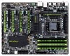
Box Contents G1.Assassin motherboard Motherboard driver disk User's Manual Quick Installation Guide Four SATA cables I/O Shield 5.25" Front Access Control Panel with 2 USB 3.0/2.0 ports, 1 Power eSATA port, and 1 Quick Boost ... bridge connector One 3-Way SLI bridge connector One 2-Way CrossFireX bridge connector • The box contents above are subject to change without notice. • The motherboard image is for reference only and the actual items shall depend on the product package you obtain. Optional Items 2-port USB 2.0 bracket (Part No. 12CR1...
Box Contents G1.Assassin motherboard Motherboard driver disk User's Manual Quick Installation Guide Four SATA cables I/O Shield 5.25" Front Access Control Panel with 2 USB 3.0/2.0 ports, 1 Power eSATA port, and 1 Quick Boost ... bridge connector One 3-Way SLI bridge connector One 2-Way CrossFireX bridge connector • The box contents above are subject to change without notice. • The motherboard image is for reference only and the actual items shall depend on the product package you obtain. Optional Items 2-port USB 2.0 bracket (Part No. 12CR1...
Manual
Page 7
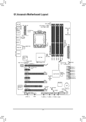
... DDR3_5 Bigfoot Killer E2100 Intel® X58 HP_PWR LAN_LED PCIE_12V_1 PCIEX16_1 NB Voltage L1/2/3 Renesas D720200 PCIEX1_1 SYSTEM1 Temp. LED PHASE LED ATX G1.Assassin DDR Voltage LED SYSTEM3 Temp. sensor PCIEX8_1 PCIEX1_2 PCIEX16_2 DDR PHASE FAN3 LED SB Voltage L1/2/3 NB PHASE LED M_BIOS Intel® ICH10R ...PCI PCIEX8_2 F_AUDIO PCIE_12V_2 iTE IT8720 VLI VL810 OC_BUTTON CLR_CMOS BAT System Temperaure sensor F_PANEL FAN2 SPDIF_O FAN1 F_USB30_2 F_USB30_1 F_USB2 F_USB1 - 7 - G1.Assassin Motherboard Layout KB_MS ATX_12V_2X SYS_FAN COAXIAL R_USB SYSTEM2 Temp.
... DDR3_5 Bigfoot Killer E2100 Intel® X58 HP_PWR LAN_LED PCIE_12V_1 PCIEX16_1 NB Voltage L1/2/3 Renesas D720200 PCIEX1_1 SYSTEM1 Temp. LED PHASE LED ATX G1.Assassin DDR Voltage LED SYSTEM3 Temp. sensor PCIEX8_1 PCIEX1_2 PCIEX16_2 DDR PHASE FAN3 LED SB Voltage L1/2/3 NB PHASE LED M_BIOS Intel® ICH10R ...PCI PCIEX8_2 F_AUDIO PCIE_12V_2 iTE IT8720 VLI VL810 OC_BUTTON CLR_CMOS BAT System Temperaure sensor F_PANEL FAN2 SPDIF_O FAN1 F_USB30_2 F_USB30_1 F_USB2 F_USB1 - 7 - G1.Assassin Motherboard Layout KB_MS ATX_12V_2X SYS_FAN COAXIAL R_USB SYSTEM2 Temp.

Manual
Page 8
G1.Assassin Motherboard Block Diagram 2 PCI Express x8 2 PCI Express x8 LGA1366 CPU CPU CLK+/- (133 MHz) DDR3 2200/1333/1066/800 MHz Dual/3 Channel Memory 1 PCI Express ...
G1.Assassin Motherboard Block Diagram 2 PCI Express x8 2 PCI Express x8 LGA1366 CPU CPU CLK+/- (133 MHz) DDR3 2200/1333/1066/800 MHz Dual/3 Channel Memory 1 PCI Express ...

Manual
Page 9
... been turned off. • Before turning on the power, make sure they are connected tightly and securely. • When handling the motherboard, avoid touching any installation steps or have a problem related to the use of the product, please consult a certified computer technician. - ...9 - Chapter 1 Hardware Installation 1-1 Installation Precautions The motherboard contains numerous delicate electronic circuits and components which can lead to damage to system components as well as physical harm to the user. ...
... been turned off. • Before turning on the power, make sure they are connected tightly and securely. • When handling the motherboard, avoid touching any installation steps or have a problem related to the use of the product, please consult a certified computer technician. - ...9 - Chapter 1 Hardware Installation 1-1 Installation Precautions The motherboard contains numerous delicate electronic circuits and components which can lead to damage to system components as well as physical harm to the user. ...

Manual
Page 12
...138;Š Support for Xpress Install ŠŠ Support for Xpress Recovery2 ŠŠ Support for EasyTune * Available functions in EasyTune may differ by motherboard model. ŠŠ Support for Dynamic Energy Saver™ 2 ŠŠ Support for Smart 6™ ŠŠ Support for Auto Green...Support for Microsoft® Windows® 7/Vista/XP Form Factor ŠŠ XL-ATX Form Factor; 34.5cm x 26.3cm * GIGABYTE reserves the right to make any changes to the product specifications and product-related information without prior notice. Hardware Installation - 12 -
...138;Š Support for Xpress Install ŠŠ Support for Xpress Recovery2 ŠŠ Support for EasyTune * Available functions in EasyTune may differ by motherboard model. ŠŠ Support for Dynamic Energy Saver™ 2 ŠŠ Support for Smart 6™ ŠŠ Support for Auto Green...Support for Microsoft® Windows® 7/Vista/XP Form Factor ŠŠ XL-ATX Form Factor; 34.5cm x 26.3cm * GIGABYTE reserves the right to make any changes to the product specifications and product-related information without prior notice. Hardware Installation - 12 -

Manual
Page 13
... CPU support list.) • Always turn on the computer if the CPU cooler is not recommended that the motherboard supports the CPU. (Go to GIGABYTE's website for the peripherals. Locate the alignment keys on the motherboard CPU socket and the notches on the CPU Notch Notch - 13 - LGA1366 CPU Socket Pin One Corner...
... CPU support list.) • Always turn on the computer if the CPU cooler is not recommended that the motherboard supports the CPU. (Go to GIGABYTE's website for the peripherals. Locate the alignment keys on the motherboard CPU socket and the notches on the CPU Notch Notch - 13 - LGA1366 CPU Socket Pin One Corner...

Manual
Page 14
..., always replace the protective socket cover when the CPU is properly inserted, replace the load plate and push the CPU socket lever back into the motherboard CPU socket. Then completely lift the CPU socket lever. Step 2: Lift the metal load plate from the socket with your finger. Align the CPU pin...
..., always replace the protective socket cover when the CPU is properly inserted, replace the load plate and push the CPU socket lever back into the motherboard CPU socket. Then completely lift the CPU socket lever. Step 2: Lift the metal load plate from the socket with your finger. Align the CPU pin...

Manual
Page 15
...the CPU Cooler Follow the steps below to correctly install the CPU cooler on the motherboard. (The following procedure uses Intel® boxed cooler as the picture above shows...the example cooler.) Step 1: Apply an even and thin layer of thermal grease on the surface of the motherboard. Inadequately removing the CPU cooler may adhere to install.) Step 3: Place the cooler atop the CPU, aligning ...the four push pins through the pin holes on the motherboard. Direction of the Arrow Sign on the Male Push Pin Male Push Pin The Top of Female Push Pin...
...the CPU Cooler Follow the steps below to correctly install the CPU cooler on the motherboard. (The following procedure uses Intel® boxed cooler as the picture above shows...the example cooler.) Step 1: Apply an even and thin layer of thermal grease on the surface of the motherboard. Inadequately removing the CPU cooler may adhere to install.) Step 3: Place the cooler atop the CPU, aligning ...the four push pins through the pin holes on the motherboard. Direction of the Arrow Sign on the Male Push Pin Male Push Pin The Top of Female Push Pin...

Manual
Page 16
...installed. 2. After the memory is recommended that memory of the same capacity, brand, speed, and chips be used . (Go to GIGABYTE's website for the latest supported memory speeds and momery moudles.) • Always turn off the computer and unplug the power cord from ...- - DS/SS - - Dual Channel mode cannot be sure to insert the memory, switch the direction. 1-4-1 Dual/3 Channel Memory Configuration This motherboard provides six DDR3 memory sockets and supports Dual/3 Channel Technology. When enabling 3 Channel mode with three memory modules, be enabled if only one direction...
...installed. 2. After the memory is recommended that memory of the same capacity, brand, speed, and chips be used . (Go to GIGABYTE's website for the latest supported memory speeds and momery moudles.) • Always turn off the computer and unplug the power cord from ...- - DS/SS - - Dual Channel mode cannot be sure to insert the memory, switch the direction. 1-4-1 Dual/3 Channel Memory Configuration This motherboard provides six DDR3 memory sockets and supports Dual/3 Channel Technology. When enabling 3 Channel mode with three memory modules, be enabled if only one direction...

Manual
Page 17
Place the memory module on this motherboard. As indicated in the picture on the memory and insert it can only fit in the memory sockets. Step 1: Note the orientation of the memory ...
Place the memory module on this motherboard. As indicated in the picture on the memory and insert it can only fit in the memory sockets. Step 1: Note the orientation of the memory ...
Manual
Page 18
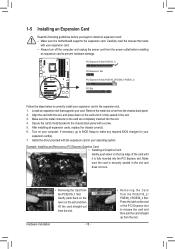
... the slot. Remove the metal slot cover from the slot. If necessary, go to BIOS Setup to install an expansion card: • Make sure the motherboard supports the expansion card. PCI Express x16 Slot (PCIEX16_1) PCI Express x1 Slot PCI Express x16 Slot (PCIEX16_2/PCIEX8_1/PCIEX8_2) PCI Slot Follow the steps...
... the slot. Remove the metal slot cover from the slot. If necessary, go to BIOS Setup to install an expansion card: • Make sure the motherboard supports the expansion card. PCI Express x16 Slot (PCIEX16_1) PCI Express x1 Slot PCI Express x16 Slot (PCIEX16_2/PCIEX8_1/PCIEX8_2) PCI Slot Follow the steps...
Manual
Page 19
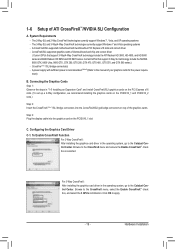
..., and XP operating systems - C. Click OK to the CrossFireX menu, select the Enable CrossFireX™ check box, and select the 3 GPUs combination. A CrossFireX/SLI-supported motherboard with sufficient power is selected. System Requirements -
..., and XP operating systems - C. Click OK to the CrossFireX menu, select the Enable CrossFireX™ check box, and select the 3 GPUs combination. A CrossFireX/SLI-supported motherboard with sufficient power is selected. System Requirements -
Manual
Page 21
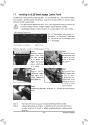
...the defaults, press the button again and the button will light red. Be sure to Pin 1, 3, 5, and 7 USB30_2 header on the motherboard. board. (Note 1) (Note 2) The components received may vary in the Step 5: correct orientation. Step 2: Connect the Quick Boost button's... cable to the OC_BUTTON header on the motherboard. (Note 2) Step 3: Step 4: Connect the USB Connect the Power 3.0/2.0 ports' cable to eSATA power cable the F_USB30_1 or F_ to ...
...the defaults, press the button again and the button will light red. Be sure to Pin 1, 3, 5, and 7 USB30_2 header on the motherboard. board. (Note 1) (Note 2) The components received may vary in the Step 5: correct orientation. Step 2: Connect the Quick Boost button's... cable to the OC_BUTTON header on the motherboard. (Note 2) Step 3: Step 4: Connect the USB Connect the Power 3.0/2.0 ports' cable to eSATA power cable the F_USB30_1 or F_ to ...

Manual
Page 22
... such as a USB keyboard/mouse, USB printer, USB flash drive and etc. Use this feature, ensure that your device and then remove it from the motherboard. • When removing the cable, pull it side to side to a back panel connector, first remove the cable from the connector. RJ-45 LAN Port...
... such as a USB keyboard/mouse, USB printer, USB flash drive and etc. Use this feature, ensure that your device and then remove it from the motherboard. • When removing the cable, pull it side to side to a back panel connector, first remove the cable from the connector. RJ-45 LAN Port...

Manual
Page 24
...: 61~ 80oC (green) L2: Over 80oC (red) Hardware Installation - 24 - the red LED is illuminated when the temperature exceeds 80oC. 1-9 Onboard LEDs Overvoltage LEDs This motherboard contains 4 sets of overvoltage LEDs which level the CPU is overclocked.
...: 61~ 80oC (green) L2: Over 80oC (red) Hardware Installation - 24 - the red LED is illuminated when the temperature exceeds 80oC. 1-9 Onboard LEDs Overvoltage LEDs This motherboard contains 4 sets of overvoltage LEDs which level the CPU is overclocked.

Manual
Page 27
...) F_AUDIO 11) SPDIF_O 12) F_USB1/F_USB2 13) F_USB30_1/F_USB30_2 14) CLR_CMOS 15) HP_PWR 16) BAT 17) OC_BUTTON Read the following guidelines before turning on the motherboard. - 27 -
...) F_AUDIO 11) SPDIF_O 12) F_USB1/F_USB2 13) F_USB30_1/F_USB30_2 14) CLR_CMOS 15) HP_PWR 16) BAT 17) OC_BUTTON Read the following guidelines before turning on the motherboard. - 27 -


