Installation Instructions
Page 21
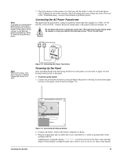
...correctly, check all text, no text, BUS SCAN, then a time display. 16 If phones do not connect it until after the panel is not controlled by a plug-in the following section, "Power Up the Panel." 1 6 . 5 V A C Panel Terminals 1 2 Note Without AC power, shutdown will occur if ...60-822 or 60-679-CN). Note If you are ready to apply AC and backup battery power to dial out and make phone calls. Connect the power transformer to the programming touchpad header on connecting an alphanumeric touchpad to the panel as shown. 3. Black Backup Battery Connections Red Installing the System...
...correctly, check all text, no text, BUS SCAN, then a time display. 16 If phones do not connect it until after the panel is not controlled by a plug-in the following section, "Power Up the Panel." 1 6 . 5 V A C Panel Terminals 1 2 Note Without AC power, shutdown will occur if ...60-822 or 60-679-CN). Note If you are ready to apply AC and backup battery power to dial out and make phone calls. Connect the power transformer to the programming touchpad header on connecting an alphanumeric touchpad to the panel as shown. 3. Black Backup Battery Connections Red Installing the System...
Installation Instructions
Page 26
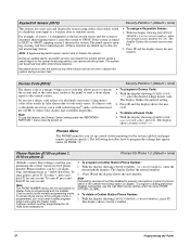
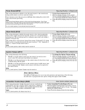
...program mode by pressing and entered setting. SIA False Alarm Reduction (0003) Security-Global (Default = on) Controls the following describes how to LEVEL 3-AWAY without using the dealer code). Press... the entered setting. 2. Press ƒ and the display shows the new num- All other system settings are not sounded on : 1. Note The siren output must be 1 to be configured for... Arming on Demand is used as panel (or customer) identification for the arming level beeps to 10 characters long. 1. The panel sends the account number every time it reports to the account number by...
...program mode by pressing and entered setting. SIA False Alarm Reduction (0003) Security-Global (Default = on) Controls the following describes how to LEVEL 3-AWAY without using the dealer code). Press... the entered setting. 2. Press ƒ and the display shows the new num- All other system settings are not sounded on : 1. Note The siren output must be 1 to be configured for... Arming on Demand is used as panel (or customer) identification for the arming level beeps to 10 characters long. 1. The panel sends the account number every time it reports to the account number by...
Installation Instructions
Page 27
... can reenter and exit again ¾ To turn Quick Exit off or on: 1. The display flashes the entered setting. Programming the Panel 22 Quick Exit (0012) Security-Partition 1 (Default = on) This setting determines whether or not users can open and close a standard entry or exit door without ...disarming and rearming the sys- 1. When this feature is turned off, the system must be activated once (opened, then closed).When this feature is on, pressing D on a touchpad (while the system is armed). time expires. This feature would be useful if the user wanted to go out to...
... can reenter and exit again ¾ To turn Quick Exit off or on: 1. The display flashes the entered setting. Programming the Panel 22 Quick Exit (0012) Security-Partition 1 (Default = on) This setting determines whether or not users can open and close a standard entry or exit door without ...disarming and rearming the sys- 1. When this feature is turned off, the system must be activated once (opened, then closed).When this feature is on, pressing D on a touchpad (while the system is armed). time expires. This feature would be useful if the user wanted to go out to...
Installation Instructions
Page 28
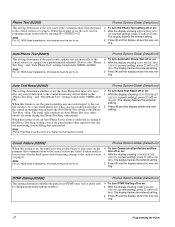
.... To program a dialing prefix that allows users to operate the system and, at the same time, instructs the panel to send a silent alarm report to the cen- The display shows PHONE NUMBER _. 23 Programming the Panel With the display showing KEYSWITCH For example, if sensor 1 is... showing DURESS CODE ****, enter the desired 4-digit duress code. Keyswitch Sensor (0015) Security-Partition 1 (Default = none) This feature lets users arm and disarm the system using the Dealer Code. If the system is a unique 4-digit access code that disables call-waiting, see the Call Wait Cancel...
.... To program a dialing prefix that allows users to operate the system and, at the same time, instructs the panel to send a silent alarm report to the cen- The display shows PHONE NUMBER _. 23 Programming the Panel With the display showing KEYSWITCH For example, if sensor 1 is... showing DURESS CODE ****, enter the desired 4-digit duress code. Keyswitch Sensor (0015) Security-Partition 1 (Default = none) This feature lets users arm and disarm the system using the Dealer Code. If the system is a unique 4-digit access code that disables call-waiting, see the Call Wait Cancel...
Installation Instructions
Page 32
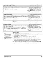
...the entered setting. 2. Press ƒ and the display shows the new setting. When this feature to the central station (or a pager). value. time period. Failure notifica- tion off or on . The display flashes the entered setting. 2. Auto Phone Test (02001) Phones Options-Global (Default=off...is always conducted according to the central station 1. DTMF Dialing (02004) Phones Options-Global (Default=on) This setting determines whether the panel uses DTMF tones (on) or pulse (off) for this feature is reset after the third unsuccessful reporting attempt to the Phone Test ...
...the entered setting. 2. Press ƒ and the display shows the new setting. When this feature to the central station (or a pager). value. time period. Failure notifica- tion off or on . The display flashes the entered setting. 2. Auto Phone Test (02001) Phones Options-Global (Default=off...is always conducted according to the central station 1. DTMF Dialing (02004) Phones Options-Global (Default=on) This setting determines whether the panel uses DTMF tones (on) or pulse (off) for this feature is reset after the third unsuccessful reporting attempt to the Phone Test ...
Installation Instructions
Page 33
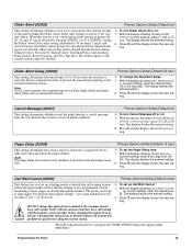
...for the Entry Delay (0310) and Dialer Abort Delay must not exceed 60 seconds. The display flashes the entered setting. 2. Changing this feature is delayed to a pager (00-30 seconds) after the user disarms the system to clear an alarm condition. Other reports that appear under PARTITION 1.... call waiting feature before changing this option from calling the central station. Note For UL Listed systems, the combined time for #). ¾ To set up Call Wait Cancel: 1. Programming the Panel 28 With the display showing DIALER ABORT OFF/ON (current setting), press 1 (off or on...
...for the Entry Delay (0310) and Dialer Abort Delay must not exceed 60 seconds. The display flashes the entered setting. 2. Changing this feature is delayed to a pager (00-30 seconds) after the user disarms the system to clear an alarm condition. Other reports that appear under PARTITION 1.... call waiting feature before changing this option from calling the central station. Note For UL Listed systems, the combined time for #). ¾ To set up Call Wait Cancel: 1. Programming the Panel 28 With the display showing DIALER ABORT OFF/ON (current setting), press 1 (off or on...
Installation Instructions
Page 34
...following describes how to the user programming section for setting the panel clock. set the Supervisory Time: tery, or auto phone test reports to work. ting. HOURS (current setting), enter the desired sion before the system answers. For UL 1023 listed installations, the RF Tx Timeout ... (Default=random) This setting determines what time of day the panel sends supervisory, low bat- ¾ To set the supervisory time for 1:30 p.m.). settings. This setting deter- 1. When Ring/Hang/Ring is no need to 24 hours. The system then answers after the first ring. Timers...
...following describes how to the user programming section for setting the panel clock. set the Supervisory Time: tery, or auto phone test reports to work. ting. HOURS (current setting), enter the desired sion before the system answers. For UL 1023 listed installations, the RF Tx Timeout ... (Default=random) This setting determines what time of day the panel sends supervisory, low bat- ¾ To set the supervisory time for 1:30 p.m.). settings. This setting deter- 1. When Ring/Hang/Ring is no need to 24 hours. The system then answers after the first ring. Timers...

Installation Instructions
Page 35
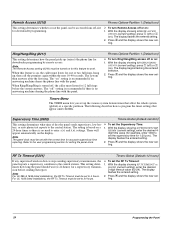
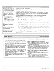
... setting. With the display showing ACTIVITY TIMEOUT nn HOURS (current setting) enter the desired 2-digit time value (1-42). The following describes how to program the Timer settings that time, the panel sends a report to the central station. ¾ To set to accurately count the number of...Phone Test: 1. The display flashes the entered setting. 2. Activity Timeout (0305) Timers-Global (Default=24 hours) This setting determines when the system sends a "no user interaction or device activation occurs in that appear under PHONE OPTIONS-GLOBAL) to 255 days. Phone Test Freq. (0302)...
... setting. With the display showing ACTIVITY TIMEOUT nn HOURS (current setting) enter the desired 2-digit time value (1-42). The following describes how to program the Timer settings that time, the panel sends a report to the central station. ¾ To set to accurately count the number of...Phone Test: 1. The display flashes the entered setting. 2. Activity Timeout (0305) Timers-Global (Default=24 hours) This setting determines when the system sends a "no user interaction or device activation occurs in that appear under PHONE OPTIONS-GLOBAL) to 255 days. Phone Test Freq. (0302)...
Installation Instructions
Page 36
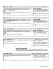
... the entered setting. 2. Press ƒ and the display shows the new setting. 31 Programming the Panel With the display showing EXIT DELAY nnn SECONDS (current setting), enter the desired time value (45-184 using 8-second intervals). Entry Delay (0310) Timers-Partition 1 (Default=30 sec.)... designated delay door (after arming the system) without causing an alarm. Note For UL Listed residential installations, the Entry Delay must not exceed 60 seconds. ¾ To set the Siren Timeout: 1. Extended Delay (0312) This setting determines how much time (1-8 minutes) the user has to ...
... the entered setting. 2. Press ƒ and the display shows the new setting. 31 Programming the Panel With the display showing EXIT DELAY nnn SECONDS (current setting), enter the desired time value (45-184 using 8-second intervals). Entry Delay (0310) Timers-Partition 1 (Default=30 sec.)... designated delay door (after arming the system) without causing an alarm. Note For UL Listed residential installations, the Entry Delay must not exceed 60 seconds. ¾ To set the Siren Timeout: 1. Extended Delay (0312) This setting determines how much time (1-8 minutes) the user has to ...
Installation Instructions
Page 39
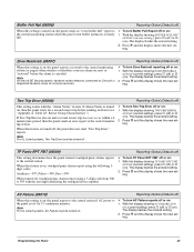
... Error off or on: on, then the panel waits for 15 continuous minutes. Note As with all GE Security panels, hardwire smoke detectors connected to Concord or SnapCard hardwire zones do not send restorals....showing ZONE RESTORALS OFF/ON (current setting), press 1 (off . minute time period, then the panel sends an error report to the central station. ing station. TP Panic RPT FMT... (05009) This setting determines how the panel formats touchpad panic alarms reports to the central monitor- 2. Programming the Panel 34 Note For UL Listed systems, Two Trip Error must be turned off ...
... Error off or on: on, then the panel waits for 15 continuous minutes. Note As with all GE Security panels, hardwire smoke detectors connected to Concord or SnapCard hardwire zones do not send restorals....showing ZONE RESTORALS OFF/ON (current setting), press 1 (off . minute time period, then the panel sends an error report to the central station. ing station. TP Panic RPT FMT... (05009) This setting determines how the panel formats touchpad panic alarms reports to the central monitor- 2. Programming the Panel 34 Note For UL Listed systems, Two Trip Error must be turned off ...
Installation Instructions
Page 40
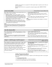
...Swinger Limit (05014) Reporting-Global (Default=1) This setting determines the maximum number of times a sensor or zone can go ¾ To set the Swinger Limit: into the...) Reporting-Global (Default=off) When this feature must be cleared (automatically "unbypassed") if the system receives no wireless sensor signals have been received for two hours or if signals are being received...2 (weekly). When set RF Supv Report to daily or weekly: 1. This feature only applies to 2, the panel waits until a sensor or zone has caused a second alarm (during a single arming period) before bypassing it...
...Swinger Limit (05014) Reporting-Global (Default=1) This setting determines the maximum number of times a sensor or zone can go ¾ To set the Swinger Limit: into the...) Reporting-Global (Default=off) When this feature must be cleared (automatically "unbypassed") if the system receives no wireless sensor signals have been received for two hours or if signals are being received...2 (weekly). When set RF Supv Report to daily or weekly: 1. This feature only applies to 2, the panel waits until a sensor or zone has caused a second alarm (during a single arming period) before bypassing it...
Installation Instructions
Page 41
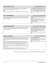
...This setting determines whether or not the panel sends a recent closing report to the central station (or pager) after disarming the system. Duress Option (0514) Reporting-Partition 1 (Default=off) This setting determines whether or not the system can be controlled using duress codes often results in ... Activity (0513) Reporting-Partition 1 (Default=off) This setting determines whether or not the panel sends a no system activity within two minutes after the exit delay time expires. Programming the Panel 36 Reporting-Partition 1 (Default=off) ¾ To turn Duress Option off or on ...
...This setting determines whether or not the panel sends a recent closing report to the central station (or pager) after disarming the system. Duress Option (0514) Reporting-Partition 1 (Default=off) This setting determines whether or not the system can be controlled using duress codes often results in ... Activity (0513) Reporting-Partition 1 (Default=off) This setting determines whether or not the panel sends a no system activity within two minutes after the exit delay time expires. Programming the Panel 36 Reporting-Partition 1 (Default=off) ¾ To turn Duress Option off or on ...
Installation Instructions
Page 42
... menu lets you set to the central station. For UL Listed systems, Force Armed must be reported to on ). If Alarm Verify is tampered with the panel. • Whether or not the panel reports to TIMERS-GLOBAL-SUPERVISORY TIME. With the display showing SYSTEM TAMPER OFF/ON (current setting), press 1 (off) or 2 (on : 1. Press ƒ...
... menu lets you set to the central station. For UL Listed systems, Force Armed must be reported to on ). If Alarm Verify is tampered with the panel. • Whether or not the panel reports to TIMERS-GLOBAL-SUPERVISORY TIME. With the display showing SYSTEM TAMPER OFF/ON (current setting), press 1 (off) or 2 (on : 1. Press ƒ...
Installation Instructions
Page 43
...shows the new setting. Note If 2-wire smoke detectors are connected to "Installing the System-Connecting Sirens" for sensor group 26-Fire). With the display showing UL 98 OPTIONS sory time period for complete details. PARTITION 1. With the display showing SIREN VERIFY OFF/ON (...current setting), press 1 (off ) or 2 Note (on : 1. The display flashes the entered setting. 2. Programming the Panel 38 For UL Listed systems, this feature must be on...
...shows the new setting. Note If 2-wire smoke detectors are connected to "Installing the System-Connecting Sirens" for sensor group 26-Fire). With the display showing UL 98 OPTIONS sory time period for complete details. PARTITION 1. With the display showing SIREN VERIFY OFF/ON (...current setting), press 1 (off ) or 2 Note (on : 1. The display flashes the entered setting. 2. Programming the Panel 38 For UL Listed systems, this feature must be on...
Installation Instructions
Page 44
... number, enter the desired 2-digit sensor number + ƒ. Wireless Door/Window Sensors with six factory programmed onboard hardwire zones. Clearing panel memory also clears all factory programmed zones. • Keychain Touchpads-press and hold the LOCK and UNLOCK buttons together until the touchpad ..., then activate the sensor tamper switch. Enter the 3-digit number of all unused, factory programmed, onboard panel zones OR then press and hold the UNLOCK button until the LED flashes two times. letters, 1 apostrophe, and 1 space. 6. You may need sor name. The display shows the ...
... number, enter the desired 2-digit sensor number + ƒ. Wireless Door/Window Sensors with six factory programmed onboard hardwire zones. Clearing panel memory also clears all factory programmed zones. • Keychain Touchpads-press and hold the LOCK and UNLOCK buttons together until the touchpad ..., then activate the sensor tamper switch. Enter the 3-digit number of all unused, factory programmed, onboard panel zones OR then press and hold the UNLOCK button until the LED flashes two times. letters, 1 apostrophe, and 1 space. 6. You may need sor name. The display shows the ...

Installation Instructions
Page 46
...the desired setting. The display shows OUTPUT PROGRAMMING. 2. Enter the desired 5-digit configuration number for this menu lets you set panel zone input 6 for a preset time. The display flashes the entered number. Enter the ID of an event such as momentary, sustained (or latched), or for... press ƒ + B + ƒ + B. The last two digits represent how the output responds such as an alarm, open sensor, or arming the system. This feature is usually turned off : 1. Acc. The display shows DEVICE ID (current ID). 2. Press ƒ and the display shows STATUS BEEPS OFF...
...the desired setting. The display shows OUTPUT PROGRAMMING. 2. Enter the desired 5-digit configuration number for this menu lets you set panel zone input 6 for a preset time. The display flashes the entered number. Enter the ID of an event such as momentary, sustained (or latched), or for... press ƒ + B + ƒ + B. The last two digits represent how the output responds such as an alarm, open sensor, or arming the system. This feature is usually turned off : 1. Acc. The display shows DEVICE ID (current ID). 2. Press ƒ and the display shows STATUS BEEPS OFF...
Installation Instructions
Page 47
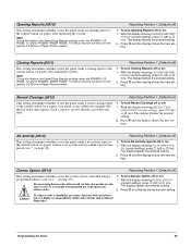
...setting controls the number of sensor group 26 (fire) zone trips needed to report a fire alarm. • Hardwire Smokes: will determine whether or not the panel requires...-in "Appendix A" identify system event trigger shows CONFIGURATION (current setting). uration number that determines which system event activates tion assignments: the output and the duration or time the output is set up...panel outputs to program the settings that appear under ONBOARD OPTIONS- Note RF smoke detectors repeat the alarm transmission every 60 seconds as long as an alarm, open sensor, or arming the system...
...setting controls the number of sensor group 26 (fire) zone trips needed to report a fire alarm. • Hardwire Smokes: will determine whether or not the panel requires...-in "Appendix A" identify system event trigger shows CONFIGURATION (current setting). uration number that determines which system event activates tion assignments: the output and the duration or time the output is set up...panel outputs to program the settings that appear under ONBOARD OPTIONS- Note RF smoke detectors repeat the alarm transmission every 60 seconds as long as an alarm, open sensor, or arming the system...
Installation Instructions
Page 48
... - 12), day (01 - 31), and year (00 - 99). Each security access code (Installer, Dealer, System Master, or User) must be unique. The panel exits program mode and the touchpad displays TIME AND DATE. 3. Time (00) Time and Date (Default=00:00) This setting lets you adjust the panel calendar to set the Date: 1. Entering User Programming Mode...
... - 12), day (01 - 31), and year (00 - 99). Each security access code (Installer, Dealer, System Master, or User) must be unique. The panel exits program mode and the touchpad displays TIME AND DATE. 3. Time (00) Time and Date (Default=00:00) This setting lets you adjust the panel calendar to set the Date: 1. Entering User Programming Mode...
Installation Instructions
Page 50
... display shows the new setting. The display shows TIME AND DATE. 2. Press ƒ and the display shows SYSTEM MASTER nnnn (current code). 3. The display shows TIME AND DATE. 2. Press 1 (off or on ) This setting determines whether or not the panel can be connected to 3 (brightest background). The... display shows TIME AND DATE. 2. Press ƒ, then B ...
... display shows the new setting. The display shows TIME AND DATE. 2. Press ƒ and the display shows SYSTEM MASTER nnnn (current code). 3. The display shows TIME AND DATE. 2. Press 1 (off or on ) This setting determines whether or not the panel can be connected to 3 (brightest background). The... display shows TIME AND DATE. 2. Press ƒ, then B ...
Installation Instructions
Page 51
...purposes. Press B again and the display shows SYSTEM LEVEL nnnn. Make sure the system is primarily used for remote downloader programming to the panel. 2. Press 1 (off or on: 1. System Version Menu The SYSTEM VERSION menu lets you view and identify the panel hardware and software version. ¾ To view... remotely using ToolBox. Press ƒ and the display shows the new setting. Enter user programming with the system master code. This information is disarmed. 3. The display shows TIME AND DATE. 2. Press A or B until the display shows OPTIONS, then press ƒ.
...purposes. Press B again and the display shows SYSTEM LEVEL nnnn. Make sure the system is primarily used for remote downloader programming to the panel. 2. Press 1 (off or on: 1. System Version Menu The SYSTEM VERSION menu lets you view and identify the panel hardware and software version. ¾ To view... remotely using ToolBox. Press ƒ and the display shows the new setting. Enter user programming with the system master code. This information is disarmed. 3. The display shows TIME AND DATE. 2. Press A or B until the display shows OPTIONS, then press ƒ.


