Installation Instructions
Page 4
... This Manual 1 Special Installation Requirements 1 UL Listed Systems ...1 UL-Canada Listed Systems ...3 Planning the Installation 3 Standard Panel ...3 Touchpads ...3 SnapCard ...3 Installing the System 4 Determine the Panel Location ...4 Total System Power and Wire Length Guidelines 5 Mounting the Panel ...6 Identify Panel Components ...7 Connecting the Panel to Earth Ground ...7 Installing Optional SnapCards ...8 Installing Optional Hardwire Input Modules (HIMs 8 Connecting Detection Devices to Panel Zone Inputs...
... This Manual 1 Special Installation Requirements 1 UL Listed Systems ...1 UL-Canada Listed Systems ...3 Planning the Installation 3 Standard Panel ...3 Touchpads ...3 SnapCard ...3 Installing the System 4 Determine the Panel Location ...4 Total System Power and Wire Length Guidelines 5 Mounting the Panel ...6 Identify Panel Components ...7 Connecting the Panel to Earth Ground ...7 Installing Optional SnapCards ...8 Installing Optional Hardwire Input Modules (HIMs 8 Connecting Detection Devices to Panel Zone Inputs...
Installation Instructions
Page 6
... testing this manual refers you to record hardware layout and software programming settings. This security system can be used as a wire warning system, an intrusion alarm system, an emergency notification system, or any combination of the three. UL Listed Systems This section describes...UL Listed systems. Basic System • Control Panel (60-806, 60-806-95R) • Backup Battery, 12 VDC, 4 AH (60-681) • SuperBus 2000 2x16 LCD Touchpad (60-746-01), SuperBus 2000 Fixed Display Touchpad (60-820), SuperBus 2000 2x20 LCD Touchpad (60-803), or SuperBus 2000 2x20 VFD Touchpad (60-804)...
... testing this manual refers you to record hardware layout and software programming settings. This security system can be used as a wire warning system, an intrusion alarm system, an emergency notification system, or any combination of the three. UL Listed Systems This section describes...UL Listed systems. Basic System • Control Panel (60-806, 60-806-95R) • Backup Battery, 12 VDC, 4 AH (60-681) • SuperBus 2000 2x16 LCD Touchpad (60-746-01), SuperBus 2000 Fixed Display Touchpad (60-820), SuperBus 2000 2x20 LCD Touchpad (60-803), or SuperBus 2000 2x20 VFD Touchpad (60-804)...
Installation Instructions
Page 20
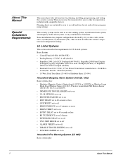
...and make phone calls. Connect the green, brown, gray, and red flying leads from off the phone switch places the panel ahead of the phone system which prevents panel access from phones on the premises for dial tone and the ability to dial out and make corrections where necessary. Connecting the...from the block and splice them to the black and white (or yellow) wires of this manual if problems persist. Proceed to panel terminals 18, 19, 20, and 21 (see C in Figure 16). 5. However, the panel can still be accessed from the DB-8 cord to the "Troubleshooting" section of the 4-conductor...
...and make phone calls. Connect the green, brown, gray, and red flying leads from off the phone switch places the panel ahead of the phone system which prevents panel access from phones on the premises for dial tone and the ability to dial out and make corrections where necessary. Connecting the...from the block and splice them to the black and white (or yellow) wires of this manual if problems persist. Proceed to panel terminals 18, 19, 20, and 21 (see C in Figure 16). 5. However, the panel can still be accessed from the DB-8 cord to the "Troubleshooting" section of the 4-conductor...
Installation Instructions
Page 21
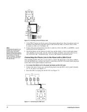
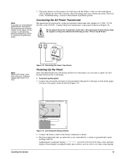
...steps described in the power transformer at this manual if problems persist. Connect the red and black battery leads (included with panel) to the battery terminals as shown in ...controlled by a plug-in stepdown transformer that is powered up the panel: 1. Fixed display touchpads briefly show all wiring and correct where necessary. left area of this time. Black Backup Battery Connections Red Installing the System... to the panel as shown. 3. Plug the transformer into an outlet that supplies 16.5 VAC, 25 VA (60-822 or 60-679-CN). Check the phones on the panel, do not...
...steps described in the power transformer at this manual if problems persist. Connect the red and black battery leads (included with panel) to the battery terminals as shown in ...controlled by a plug-in stepdown transformer that is powered up the panel: 1. Fixed display touchpads briefly show all wiring and correct where necessary. left area of this time. Black Backup Battery Connections Red Installing the System... to the panel as shown. 3. Plug the transformer into an outlet that supplies 16.5 VAC, 25 VA (60-822 or 60-679-CN). Check the phones on the panel, do not...
Installation Instructions
Page 25
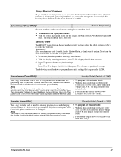
...ciated with phone numbers can be used in conjunction with downloader pro- ¾ To program a Downloader Code: gramming. Programming the Panel 20 For example this manual appear in order to perform any programming. Press ƒ again to advance to global settings OR Press A or B to ...the right. Shortcut numbers in this heading shows the Downloader Code shortcut to be deleted from panel memory. Each security access code (Installer, Dealer, System Master, or User) must have the panel account number 1. Do not use the same combination of numbers for that appear under GLOBAL....
...ciated with phone numbers can be used in conjunction with downloader pro- ¾ To program a Downloader Code: gramming. Programming the Panel 20 For example this manual appear in order to perform any programming. Press ƒ again to advance to global settings OR Press A or B to ...the right. Shortcut numbers in this heading shows the Downloader Code shortcut to be deleted from panel memory. Each security access code (Installer, Dealer, System Master, or User) must have the panel account number 1. Do not use the same combination of numbers for that appear under GLOBAL....


