Installation Instructions
Page 1
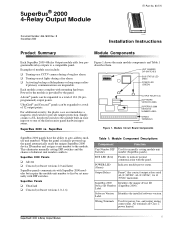
SuperBus® 2000 4-Relay Output Module ITI Part No. 60-770 Document Number: 466-1608 Rev. u Activating backup cellular phones or long-range radios if primary communications are Class 2 power limited. Simply connect a UL listed reed switch to the module built-in zone input or to a total of module uses include: u Turning on exit lights during a burglary alarm. SuperBus Figure 1 shows the...
SuperBus® 2000 4-Relay Output Module ITI Part No. 60-770 Document Number: 466-1608 Rev. u Activating backup cellular phones or long-range radios if primary communications are Class 2 power limited. Simply connect a UL listed reed switch to the module built-in zone input or to a total of module uses include: u Turning on exit lights during a burglary alarm. SuperBus Figure 1 shows the...
Installation Instructions
Page 3
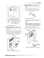
...Secure the back-plate to the cabinet using three ¼-inch #6-32 self-tapping screws (not included). Support Standoff 4. Note The two mounting clips in the top-right corner of the cabinet (Figure 6). Mounting Module in a Concord Cabinet 1. Remove and discard the module cover (Figure 2). 3. PANEL END MODULE...shown in Concord Cabinet SuperBus® 2000 4-Relay Output Module 3 Slide the module back-plate onto the two...Turn the module upside down and line up and onto the cabinet side tab. Remove AC panel power and disconnect the backup battery. 2. Gently press the module...
...Secure the back-plate to the cabinet using three ¼-inch #6-32 self-tapping screws (not included). Support Standoff 4. Note The two mounting clips in the top-right corner of the cabinet (Figure 6). Mounting Module in a Concord Cabinet 1. Remove and discard the module cover (Figure 2). 3. PANEL END MODULE...shown in Concord Cabinet SuperBus® 2000 4-Relay Output Module 3 Slide the module back-plate onto the two...Turn the module upside down and line up and onto the cabinet side tab. Remove AC panel power and disconnect the backup battery. 2. Gently press the module...
Installation Instructions
Page 4
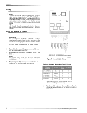
... 16 17 18 ZONE COM ZONE 1 GND** (BLK) BUS B (WHT) BUS A (GRN) +12 VDC* (RED) NO 4 COM 4 NC 4 NO 3 COM 3 NC 3 NO 2 COM 2 NC 2 NO 1 COM 1 NC 1 Important! Note For specific wiring details, see the device Installation Instructions. 4 SuperBus® 2000 4-Relay Output Module Auxiliary power supplies.... Wire that extends beyond the cable jacket must be installed as shown in Figures 7 and 8. Turn off (or disconnect) the panel power and disconnect the panel backup battery(s). 2. Wire multiple modules in "daisy-chain" fashion (in Figure 7 and Table 4. OR (B) Class 2, Class 3, ...
... 16 17 18 ZONE COM ZONE 1 GND** (BLK) BUS B (WHT) BUS A (GRN) +12 VDC* (RED) NO 4 COM 4 NC 4 NO 3 COM 3 NC 3 NO 2 COM 2 NC 2 NO 1 COM 1 NC 1 Important! Note For specific wiring details, see the device Installation Instructions. 4 SuperBus® 2000 4-Relay Output Module Auxiliary power supplies.... Wire that extends beyond the cable jacket must be installed as shown in Figures 7 and 8. Turn off (or disconnect) the panel power and disconnect the panel backup battery(s). 2. Wire multiple modules in "daisy-chain" fashion (in Figure 7 and Table 4. OR (B) Class 2, Class 3, ...
Installation Instructions
Page 6
... Bus Communication This section describes how to the module ZONE 1 (17) and ZONE COMMON (18) terminals (Figure 9). Existing Installations Concord Panels- Advent Panels- 1. Verify that all switches to "M" (on for one second. Verify that all wiring between the panel, touchpad and module is correct. 6 SuperBus® 2000 4-Relay Output Module Both the green and red LEDs will remain...
... Bus Communication This section describes how to the module ZONE 1 (17) and ZONE COMMON (18) terminals (Figure 9). Existing Installations Concord Panels- Advent Panels- 1. Verify that all switches to "M" (on for one second. Verify that all wiring between the panel, touchpad and module is correct. 6 SuperBus® 2000 4-Relay Output Module Both the green and red LEDs will remain...

Installation Instructions
Page 7
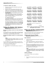
...for one second, then the green POWER LED will remain on . Output(s) activate 1. Make sure the zone has been "learned" into program mode. Replace the module. Output may have failed or been overloaded. SuperBus® 2000 4-Relay Output Module 7 Enter your Install Code (default 0123). 6. Verify nonconflicting bus ...the backup battery, and see specific panel Installation Instructions). 4. Both the green and red LEDs turn on " time and if the triggering event for bus devices with the or module and/or same unit number setting. Press 8 for Program Menu. 5. Press 0 for ...
...for one second, then the green POWER LED will remain on . Output(s) activate 1. Make sure the zone has been "learned" into program mode. Replace the module. Output may have failed or been overloaded. SuperBus® 2000 4-Relay Output Module 7 Enter your Install Code (default 0123). 6. Verify nonconflicting bus ...the backup battery, and see specific panel Installation Instructions). 4. Both the green and red LEDs turn on " time and if the triggering event for bus devices with the or module and/or same unit number setting. Press 8 for Program Menu. 5. Press 0 for ...
Installation Instructions
Page 8
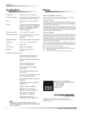
...(-34° to 60° C) Operating Temperature: 32° to 140° F (0° to 60° C), up to 140° F (60° C) under ... of Interlogix, Inc. SuperBus® 2000 4-Relay Output Module Relay contacts rated 4A ...@ 24VDC, 4A @ 24VAC, 1A @ 70VAC maximum. These limits are designed to provide reasonable protection against harmful interference when the equipment is no guarantee that interference will be determined by turning... supervised, fire-rated, hardwire zone Outputs: Four, panel programmable outputs with the limits for a ...
...(-34° to 60° C) Operating Temperature: 32° to 140° F (0° to 60° C), up to 140° F (60° C) under ... of Interlogix, Inc. SuperBus® 2000 4-Relay Output Module Relay contacts rated 4A ...@ 24VDC, 4A @ 24VAC, 1A @ 70VAC maximum. These limits are designed to provide reasonable protection against harmful interference when the equipment is no guarantee that interference will be determined by turning... supervised, fire-rated, hardwire zone Outputs: Four, panel programmable outputs with the limits for a ...


