Gateway Quick Start Guide for Windows 7
Page 11
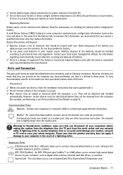
... computer to a network ('LAN') or certain high-speed Internet connections. Read the precautions on Gateway computers. A small lithium battery ('CMOS' battery) in your battery. Contact your computer is ...to connect many peripheral devices to your local waste management officials for example: keyboard, printer, scanner). IEEE 1394 (FireWire) - Before disposing of the batteries ...or scanners. Expansion Ports USB (Universal Serial Bus) - Communication Ports Network - Replacing Batteries Battery packs can affect the performance of explosion if the battery is slightly ...
... computer to a network ('LAN') or certain high-speed Internet connections. Read the precautions on Gateway computers. A small lithium battery ('CMOS' battery) in your battery. Contact your computer is ...to connect many peripheral devices to your local waste management officials for example: keyboard, printer, scanner). IEEE 1394 (FireWire) - Before disposing of the batteries ...or scanners. Expansion Ports USB (Universal Serial Bus) - Communication Ports Network - Replacing Batteries Battery packs can affect the performance of explosion if the battery is slightly ...
Gateway Quick Start Guide for Windows 7
Page 53
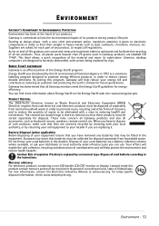
... are correctly recycled by checking with screws being replaced by an incorrect type. Gateway is an official partner of our products. Thus, all accessories, such as a voluntary labelling program designed to be fitted in 1992 as keyboard, mouse, speakers, remote control, etc. ENVIRONMENT GATEWAY'S COMMITMENT TO ENVIRONMENTAL PROTECTION Environment has been at the heart...
... are correctly recycled by checking with screws being replaced by an incorrect type. Gateway is an official partner of our products. Thus, all accessories, such as a voluntary labelling program designed to be fitted in 1992 as keyboard, mouse, speakers, remote control, etc. ENVIRONMENT GATEWAY'S COMMITMENT TO ENVIRONMENTAL PROTECTION Environment has been at the heart...
Gateway Quick Start Guide for Windows 7
Page 55
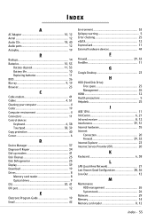
...12 Aerial 12 Audio CDs 18, 40 Audio ports 12 Autoplay 19 B Backups 14 Batteries 10, 53 Battery disposal 11, 53 Battery life 10 Replacing batteries 11 BIOS 36 Blu-ray 9, 19 Browser 23 C Cable modem 41 Cables 4, 51 Cleaning your computer 4 Codec 19 Computer environment 4...Infrared receiver 8, 12 Interference 39, 51 Internal hardware 35 Internet Connection 20 Firewall 29, 32 Internet Explorer 23 Internet Service Provider (ISP 20 K Keyboard 6, 38 L LAN (Local Area Network 21 Last Known Good Configuration 28, 36 Line-Out 12 M Maintenance HDD management 26 System tools 26...
...12 Aerial 12 Audio CDs 18, 40 Audio ports 12 Autoplay 19 B Backups 14 Batteries 10, 53 Battery disposal 11, 53 Battery life 10 Replacing batteries 11 BIOS 36 Blu-ray 9, 19 Browser 23 C Cable modem 41 Cables 4, 51 Cleaning your computer 4 Codec 19 Computer environment 4...Infrared receiver 8, 12 Interference 39, 51 Internal hardware 35 Internet Connection 20 Firewall 29, 32 Internet Explorer 23 Internet Service Provider (ISP 20 K Keyboard 6, 38 L LAN (Local Area Network 21 Last Known Good Configuration 28, 36 Line-Out 12 M Maintenance HDD management 26 System tools 26...
Service Guide
Page 4
... 56 Replacing the keyboard cover 58 Replacing the multimedia board 60 Replacing the keyboard 62 Replacing the LCD panel assembly 64 Replacing the palm rest 68 Replacing the speakers 72 Replacing the touchpad board 74 Replacing the modem board 77 Replacing the USB board 80 Replacing the Bluetooth module 83 Replacing the system board 86 Replacing the cooling assembly 89 Replacing the processor 92 Replacing the...
... 56 Replacing the keyboard cover 58 Replacing the multimedia board 60 Replacing the keyboard 62 Replacing the LCD panel assembly 64 Replacing the palm rest 68 Replacing the speakers 72 Replacing the touchpad board 74 Replacing the modem board 77 Replacing the USB board 80 Replacing the Bluetooth module 83 Replacing the system board 86 Replacing the cooling assembly 89 Replacing the processor 92 Replacing the...
Service Guide
Page 5
www.gateway.com Chapter 4: Troubleshooting 115 Diagnosing problems 116 System test procedures 117 Testing the optical drive 117 Testing the keyboard or auxiliary input device 117 Testing the memory 118 Testing the power system 118 Testing the touchpad 119 Power-On ... Memory 130 Sound 130 Power management 130 Devices 131 Keyboard and touchpad 131 Intermittent problems 132 Undetermined problems 133 Chapter 5: Connector locations 135 System board layout 136 Top view 136 Bottom view 137 Chapter 6: FRU (Field-Replaceable Unit) list 139 Introduction 140 Exploded diagram 140 FRU...
www.gateway.com Chapter 4: Troubleshooting 115 Diagnosing problems 116 System test procedures 117 Testing the optical drive 117 Testing the keyboard or auxiliary input device 117 Testing the memory 118 Testing the power system 118 Testing the touchpad 119 Power-On ... Memory 130 Sound 130 Power management 130 Devices 131 Keyboard and touchpad 131 Intermittent problems 132 Undetermined problems 133 Chapter 5: Connector locations 135 System board layout 136 Top view 136 Bottom view 137 Chapter 6: FRU (Field-Replaceable Unit) list 139 Introduction 140 Exploded diagram 140 FRU...
Service Guide
Page 49
... • Replacing the keyboard cover • Replacing the multimedia board • Replacing the keyboard • Replacing the LCD panel assembly • Replacing the palm rest • Replacing the speakers • Replacing the touchpad board • Replacing the modem board • Replacing the USB board • Replacing the Bluetooth module • Replacing the system board • Replacing the cooling assembly • Replacing the processor • Replacing the...
... • Replacing the keyboard cover • Replacing the multimedia board • Replacing the keyboard • Replacing the LCD panel assembly • Replacing the palm rest • Replacing the speakers • Replacing the touchpad board • Replacing the modem board • Replacing the USB board • Replacing the Bluetooth module • Replacing the system board • Replacing the cooling assembly • Replacing the processor • Replacing the...
Service Guide
Page 64
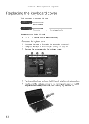
... this task: Phillips #0 screwdriver Flat screwdriver or Non-marring plastic scribe Screws removed during this task: • 3 black M2.5×6 (keyboard cover) To replace the keyboard cover: 1 Complete the steps in "Preparing the notebook" on page 47. 2 Complete the steps in "Removing the battery" on page ...48. 3 Remove the screws securing the keyboard cover. 4 Turn the notebook over and open the LCD panel to its fully extended position. ...
... this task: Phillips #0 screwdriver Flat screwdriver or Non-marring plastic scribe Screws removed during this task: • 3 black M2.5×6 (keyboard cover) To replace the keyboard cover: 1 Complete the steps in "Preparing the notebook" on page 47. 2 Complete the steps in "Removing the battery" on page ...48. 3 Remove the screws securing the keyboard cover. 4 Turn the notebook over and open the LCD panel to its fully extended position. ...

Service Guide
Page 65
... with the connector facing up, on the multimedia board, then close the LCD panel. 14 Reinstall the battery. 59 www.gateway.com Caution The keyboard cover is correctly mounted when you can run you try to close the clip to lock the cable in place. Caution If the cover ... could be using the multimedia board from the palm rest assembly and turn it by performing steps 3 and 4 of the "Replacing the multimedia board" procedure on page 60. 8 Secure the multimedia board, with the screws removed in step 3. The keyboard cover is connected to the notebook through the multimedia board cable.
... with the connector facing up, on the multimedia board, then close the LCD panel. 14 Reinstall the battery. 59 www.gateway.com Caution The keyboard cover is correctly mounted when you can run you try to close the clip to lock the cable in place. Caution If the cover ... could be using the multimedia board from the palm rest assembly and turn it by performing steps 3 and 4 of the "Replacing the multimedia board" procedure on page 60. 8 Secure the multimedia board, with the screws removed in step 3. The keyboard cover is connected to the notebook through the multimedia board cable.
Service Guide
Page 66
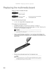
...this task: • 3 black M2.5×6 (keyboard cover) To replace the multimedia board: 1 Complete the steps in the above image. Remove this type of the "Replacing the keyboard cover" procedure on page 47. 2 Remove the keyboard cover by performing steps 2-6 of circuit board. 60... a small flat-blade screwdriver or non-marring scribe between the multimedia board and the keyboard cover's underside, and carefully pry the board loose. 4 Remove the multimedia board from the keyboard cover. CHAPTER 3: Replacing notebook components Replacing the multimedia board Tools you need to the...
...this task: • 3 black M2.5×6 (keyboard cover) To replace the multimedia board: 1 Complete the steps in the above image. Remove this type of the "Replacing the keyboard cover" procedure on page 47. 2 Remove the keyboard cover by performing steps 2-6 of circuit board. 60... a small flat-blade screwdriver or non-marring scribe between the multimedia board and the keyboard cover's underside, and carefully pry the board loose. 4 Remove the multimedia board from the keyboard cover. CHAPTER 3: Replacing notebook components Replacing the multimedia board Tools you need to the...

Service Guide
Page 67
.... 6 Insert the multimedia cable to its connector on page 58. The keyboard cover is correctly mounted when you can run you finger along the sides...damaged when you try to lock the cable in place. 7 Insert the tabs on the front side of the keyboard cover into the slots located on the top corners of the palm rest assembly, then press down on the ... cover until it clicks in step 3 of the "Replacing the keyboard cover" procedure on the multimedia board, then close the clip to close the LCD panel. 11 Reinstall the battery. 61 www.gateway.com 5 Secure the new multimedia board, with the connector...
.... 6 Insert the multimedia cable to its connector on page 58. The keyboard cover is correctly mounted when you can run you finger along the sides...damaged when you try to lock the cable in place. 7 Insert the tabs on the front side of the keyboard cover into the slots located on the top corners of the palm rest assembly, then press down on the ... cover until it clicks in step 3 of the "Replacing the keyboard cover" procedure on the multimedia board, then close the clip to close the LCD panel. 11 Reinstall the battery. 61 www.gateway.com 5 Secure the new multimedia board, with the connector...
Service Guide
Page 68
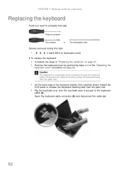
... task: • 3 black M2.5×6 (keyboard cover) To replace the keyboard: 1 Complete the steps in "Preparing the notebook" on page 58. Open the keyboard cable connector (b) and disconnect the cable (c). 62 CHAPTER 3: Replacing notebook components Replacing the keyboard Tools you need to complete this task: Phillips ...during this cable first before pulling the keyboard away from the palm rest. 3 Lift the back edge of the "Replacing the keyboard cover" procedure on page 47. 2 Remove the keyboard cover by performing steps 2-6 of the keyboard slightly, then carefully slide it toward ...
... task: • 3 black M2.5×6 (keyboard cover) To replace the keyboard: 1 Complete the steps in "Preparing the notebook" on page 58. Open the keyboard cable connector (b) and disconnect the cable (c). 62 CHAPTER 3: Replacing notebook components Replacing the keyboard Tools you need to complete this task: Phillips ...during this cable first before pulling the keyboard away from the palm rest. 3 Lift the back edge of the "Replacing the keyboard cover" procedure on page 47. 2 Remove the keyboard cover by performing steps 2-6 of the keyboard slightly, then carefully slide it toward ...
Service Guide
Page 69
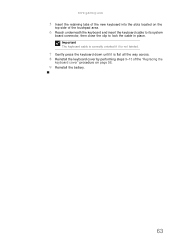
Important The keyboard cable is correctly oriented if it is not twisted. 7 Gently press the keyboard down until it is flat all the way across. 8 Reinstall the keyboard cover by performing steps 9-13 of the touchpad area. 6 Reach underneath the keyboard and insert the keyboard cable to its system board connector, then close the clip to lock the cable in place. www.gateway.com 5 Insert the retaining tabs of the new keyboard into the slots located on the top side of the "Replacing the keyboard cover" procedure on page 58. 9 Reinstall the battery. 63
Important The keyboard cable is correctly oriented if it is not twisted. 7 Gently press the keyboard down until it is flat all the way across. 8 Reinstall the keyboard cover by performing steps 9-13 of the touchpad area. 6 Reach underneath the keyboard and insert the keyboard cable to its system board connector, then close the clip to lock the cable in place. www.gateway.com 5 Insert the retaining tabs of the new keyboard into the slots located on the top side of the "Replacing the keyboard cover" procedure on page 58. 9 Reinstall the battery. 63
Service Guide
Page 70
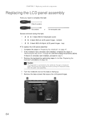
..."Removing the bay cover" on page 62. If there's no wireless card installed, proceed to the notebook through a keyboard cable. CHAPTER 3: Replacing notebook components Replacing the LCD panel assembly Tools you need to complete this task: Phillips #0 screwdriver Flat screwdriver or Non-marring plastic scribe... removed during this cable first before pulling the keyboard away from the palm rest assembly. 4 Turn the notebook over so the base is connected to step 5. 3 Remove the keyboard by performing steps 2-4 of the "Replacing the keyboard" procedure on page 49, and then unplug the...
..."Removing the bay cover" on page 62. If there's no wireless card installed, proceed to the notebook through a keyboard cable. CHAPTER 3: Replacing notebook components Replacing the LCD panel assembly Tools you need to complete this task: Phillips #0 screwdriver Flat screwdriver or Non-marring plastic scribe... removed during this cable first before pulling the keyboard away from the palm rest assembly. 4 Turn the notebook over so the base is connected to step 5. 3 Remove the keyboard by performing steps 2-4 of the "Replacing the keyboard" procedure on page 49, and then unplug the...
Service Guide
Page 73
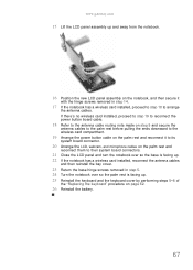
... hinge screws removed in step 5. 24 Turn the notebook over so the palm rest is facing up . 25 Reinstall the keyboard and the keyboard cover by performing steps 5-8 of the "Replacing the keyboard" procedure on the palm rest and reconnect them to their system board connectors. 21 Close the LCD panel and turn the... to step 18 to its system board connector. 20 Arrange the LCD, webcam, and microphone cables on page 62. 26 Reinstall the battery. 67 www.gateway.com 15 Lift the LCD panel assembly up and away from the notebook. 16 Position the new LCD panel assembly on the notebook, and then...
... hinge screws removed in step 5. 24 Turn the notebook over so the palm rest is facing up . 25 Reinstall the keyboard and the keyboard cover by performing steps 5-8 of the "Replacing the keyboard" procedure on the palm rest and reconnect them to their system board connectors. 21 Close the LCD panel and turn the... to step 18 to its system board connector. 20 Arrange the LCD, webcam, and microphone cables on page 62. 26 Reinstall the battery. 67 www.gateway.com 15 Lift the LCD panel assembly up and away from the notebook. 16 Position the new LCD panel assembly on the notebook, and then...
Service Guide
Page 74
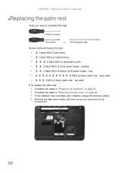
...; 1 black M2×5 (hard drive) • 1 black M2.5×6 (optical drive) • 3 black M2.5×6 (keyboard cover) • 2 black M2.5×6 (LCD panel hinges - base side) • 3 M2.5×6 black (palm rest - top side) To replace the palm rest: 1 Complete the steps in "Preparing the notebook" on page 47. 2 Complete the steps...
...; 1 black M2×5 (hard drive) • 1 black M2.5×6 (optical drive) • 3 black M2.5×6 (keyboard cover) • 2 black M2.5×6 (LCD panel hinges - base side) • 3 M2.5×6 black (palm rest - top side) To replace the palm rest: 1 Complete the steps in "Preparing the notebook" on page 47. 2 Complete the steps...
Service Guide
Page 75
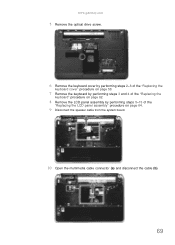
www.gateway.com 5 Remove the optical drive screw. 6 Remove the keyboard cover by performing steps 2-6 of the "Replacing the keyboard cover" procedure on page 58. 7 Remove the keyboard by performing steps 3 and 4 of the "Replacing the keyboard" procedure on page 62. 8 Remove the LCD panel assembly by performing steps 5-15 of the "Replacing the LCD panel assembly" procedure on page 64. 9 Disconnect the speaker cable from the system board. 10 Open the multimedia cable connector (a) and disconnect the cable (b). 69
www.gateway.com 5 Remove the optical drive screw. 6 Remove the keyboard cover by performing steps 2-6 of the "Replacing the keyboard cover" procedure on page 58. 7 Remove the keyboard by performing steps 3 and 4 of the "Replacing the keyboard" procedure on page 62. 8 Remove the LCD panel assembly by performing steps 5-15 of the "Replacing the LCD panel assembly" procedure on page 64. 9 Disconnect the speaker cable from the system board. 10 Open the multimedia cable connector (a) and disconnect the cable (b). 69
Service Guide
Page 77
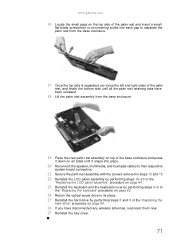
www.gateway.com 16 Locate the small gaps on the top side of the palm rest and insert a small flat-blade screwdriver or non-marring scribe into ... and 15. 22 Reinstall the LCD panel assembly by performing steps 16-23 of the "Replacing the LCD panel assembly" procedure on page 64. 23 Reinstall the keyboard and the keyboard cover by performing steps 5-8 of the "Replacing the keyboard" procedure on page 62. 24 Return the optical screw drive in its place. 25 Reinstall...
www.gateway.com 16 Locate the small gaps on the top side of the palm rest and insert a small flat-blade screwdriver or non-marring scribe into ... and 15. 22 Reinstall the LCD panel assembly by performing steps 16-23 of the "Replacing the LCD panel assembly" procedure on page 64. 23 Reinstall the keyboard and the keyboard cover by performing steps 5-8 of the "Replacing the keyboard" procedure on page 62. 24 Return the optical screw drive in its place. 25 Reinstall...
Service Guide
Page 78
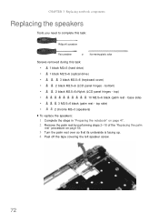
... 1 Complete the steps in "Preparing the notebook" on page 47. 2 Remove the palm rest by performing steps 2-18 of the "Replacing the palm rest" procedure on page 68. 3 Turn the palm rest over so that its underside is facing up. 4 Peel off the...215;6 black (palm rest - bottom) • 2 black M2.5×6+Nylok (LCD panel hinges - top) • 10 M2.5×6 black (palm rest - CHAPTER 3: Replacing notebook components Replacing the speakers Tools you need to complete this task: Phillips #0 screwdriver Flat screwdriver or Non-marring plastic scribe Screws removed during this task: •...
... 1 Complete the steps in "Preparing the notebook" on page 47. 2 Remove the palm rest by performing steps 2-18 of the "Replacing the palm rest" procedure on page 68. 3 Turn the palm rest over so that its underside is facing up. 4 Peel off the...215;6 black (palm rest - bottom) • 2 black M2.5×6+Nylok (LCD panel hinges - top) • 10 M2.5×6 black (palm rest - CHAPTER 3: Replacing notebook components Replacing the speakers Tools you need to complete this task: Phillips #0 screwdriver Flat screwdriver or Non-marring plastic scribe Screws removed during this task: •...
Service Guide
Page 79
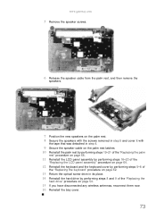
www.gateway.com 5 Remove the speaker screws. 6 Release the speaker cable from the palm rest, and then remove the speakers. 7 Position the new speakers on the palm ... page 68. 11 Reinstall the LCD panel assembly by performing steps 16-23 of the "Replacing the LCD panel assembly" procedure on page 64. 12 Reinstall the keyboard and the keyboard cover by performing steps 5-8 of the "Replacing the keyboard" procedure on page 62. 13 Return the optical screw drive in its place. 14 Reinstall...
www.gateway.com 5 Remove the speaker screws. 6 Release the speaker cable from the palm rest, and then remove the speakers. 7 Position the new speakers on the palm ... page 68. 11 Reinstall the LCD panel assembly by performing steps 16-23 of the "Replacing the LCD panel assembly" procedure on page 64. 12 Reinstall the keyboard and the keyboard cover by performing steps 5-8 of the "Replacing the keyboard" procedure on page 62. 13 Return the optical screw drive in its place. 14 Reinstall...
Service Guide
Page 80
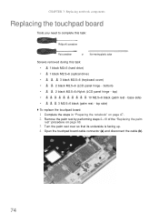
...board: 1 Complete the steps in "Preparing the notebook" on page 47. 2 Remove the palm rest by performing steps 2-18 of the "Replacing the palm rest" procedure on page 68. 3 Turn the palm rest over so that its underside is facing up. 4 Open the touchpad ... cable (b). 74 bottom) • 2 black M2.5×6+Nylok (LCD panel hinge - top) • 10 M2.5×6 black (palm rest - CHAPTER 3: Replacing notebook components Replacing the touchpad board Tools you need to complete this task: Phillips #0 screwdriver Flat screwdriver or Non-marring plastic scribe Screws removed during this task...
...board: 1 Complete the steps in "Preparing the notebook" on page 47. 2 Remove the palm rest by performing steps 2-18 of the "Replacing the palm rest" procedure on page 68. 3 Turn the palm rest over so that its underside is facing up. 4 Open the touchpad ... cable (b). 74 bottom) • 2 black M2.5×6+Nylok (LCD panel hinge - top) • 10 M2.5×6 black (palm rest - CHAPTER 3: Replacing notebook components Replacing the touchpad board Tools you need to complete this task: Phillips #0 screwdriver Flat screwdriver or Non-marring plastic scribe Screws removed during this task...


