8511725 - Gateway Service Guide
Page 3
...or replacing memory modules 7 Replacing the DVD drive 11 Replacing the cooling assembly 14 Replacing the processor 19 Replacing the IEEE 802.11 wireless card 22 Replacing the hard drive 26 Replacing the keyboard cover 29 Replacing the keyboard 31 Replacing the CMOS battery 36 Replacing the LCD panel assembly 38 Replacing the LCD panel inverter 42 Replacing the LCD panel 46 Replacing the LCD panel assembly lid 51 Replacing the palm rest 56 Replacing the modem card 59 Replacing the Bluetooth module 62 Replacing the system board 64 Replacing the external video board 67 Replacing...
...or replacing memory modules 7 Replacing the DVD drive 11 Replacing the cooling assembly 14 Replacing the processor 19 Replacing the IEEE 802.11 wireless card 22 Replacing the hard drive 26 Replacing the keyboard cover 29 Replacing the keyboard 31 Replacing the CMOS battery 36 Replacing the LCD panel assembly 38 Replacing the LCD panel inverter 42 Replacing the LCD panel 46 Replacing the LCD panel assembly lid 51 Replacing the palm rest 56 Replacing the modem card 59 Replacing the Bluetooth module 62 Replacing the system board 64 Replacing the external video board 67 Replacing...
8511725 - Gateway Service Guide
Page 39
... the LCD panel. 19 Reattach the keyboard cover by following the instructions in "Replacing the keyboard cover" on the keyboard keys along the front edge of the keyboard into place. The keyboard should easily fall into the slot under the palm rest. Tip The screw hole is facing up, then replace the keyboard screws removed in Step 8. 21 Replace the memory bay cover and wireless network bay cover. 22 Replace the keyboard screw removed in...
... the LCD panel. 19 Reattach the keyboard cover by following the instructions in "Replacing the keyboard cover" on the keyboard keys along the front edge of the keyboard into place. The keyboard should easily fall into the slot under the palm rest. Tip The screw hole is facing up, then replace the keyboard screws removed in Step 8. 21 Replace the memory bay cover and wireless network bay cover. 22 Replace the keyboard screw removed in...
8511725 - Gateway Service Guide
Page 40
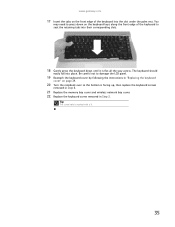
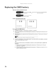
... following: a Remove the LCD panel by following the instructions in "Replacing the LCD panel assembly" on the system board, go to Step 5. 36 OR - If you do not need to complete this task: Scribe or non-marring tool 2 black (keyboard cover) 1-3 black (keyboard) To replace the CMOS battery: 1 Complete the steps in "Preparing the notebook" on page 6. 2 Remove the keyboard cover by following the instructions in "Replacing the keyboard cover" on page 29. 3 Open the keyboard compartment...
... following: a Remove the LCD panel by following the instructions in "Replacing the LCD panel assembly" on the system board, go to Step 5. 36 OR - If you do not need to complete this task: Scribe or non-marring tool 2 black (keyboard cover) 1-3 black (keyboard) To replace the CMOS battery: 1 Complete the steps in "Preparing the notebook" on page 6. 2 Remove the keyboard cover by following the instructions in "Replacing the keyboard cover" on page 29. 3 Open the keyboard compartment...

8511725 - Gateway Service Guide
Page 42
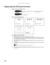
....11 wireless card by following the instructions in "Replacing the IEEE 802.11 wireless card" on page 22. 3 Remove the keyboard cover by following the instructions in "Replacing the keyboard cover" on page 29. 4 Open the keyboard compartment by following the instructions in , unplug the antenna cables from the notebook. 38 Replacing Notebook Components Replacing the LCD panel assembly Tools you need to complete this task: Scribe or non-marring tool 2 black (keyboard cover) 1-3 black (keyboard) 4 black (LCD panel hinges) To replace the LCD panel...
....11 wireless card by following the instructions in "Replacing the IEEE 802.11 wireless card" on page 22. 3 Remove the keyboard cover by following the instructions in "Replacing the keyboard cover" on page 29. 4 Open the keyboard compartment by following the instructions in , unplug the antenna cables from the notebook. 38 Replacing Notebook Components Replacing the LCD panel assembly Tools you need to complete this task: Scribe or non-marring tool 2 black (keyboard cover) 1-3 black (keyboard) 4 black (LCD panel hinges) To replace the LCD panel...
8511725 - Gateway Service Guide
Page 46
....11 wireless card" on page 22. 3 Remove the keyboard cover by following the instructions in "Replacing the keyboard cover" on page 29. 4 Open the keyboard compartment by following the instructions in "Replacing the LCD panel assembly" on page 31. OR - Replacing Notebook Components Replacing the LCD panel inverter Tools you need to complete this task: Scribe or non-marring tool 2 black (keyboard cover) 1-3 black (keyboard) 4 black (LCD panel hinges) 4 or 6 chrome (LCD panel assembly) 2 chrome (bracket) Select models only To replace the LCD panel inverter...
....11 wireless card" on page 22. 3 Remove the keyboard cover by following the instructions in "Replacing the keyboard cover" on page 29. 4 Open the keyboard compartment by following the instructions in "Replacing the LCD panel assembly" on page 31. OR - Replacing Notebook Components Replacing the LCD panel inverter Tools you need to complete this task: Scribe or non-marring tool 2 black (keyboard cover) 1-3 black (keyboard) 4 black (LCD panel hinges) 4 or 6 chrome (LCD panel assembly) 2 chrome (bracket) Select models only To replace the LCD panel inverter...

8511725 - Gateway Service Guide
Page 49
... Replace the LCD panel assembly onto the notebook by following the instructions in "Replacing the LCD panel assembly" on page 38. 18 Close the keyboard compartment by following the instructions in "Replacing the keyboard" on page 29. 20 Plug the antenna cables into the IEEE 802.11 wireless card, then replace the wireless bay cover. 45 www.gateway.com 10 Unplug both cables from the front of the LCD panel assembly removed in...
... Replace the LCD panel assembly onto the notebook by following the instructions in "Replacing the LCD panel assembly" on page 38. 18 Close the keyboard compartment by following the instructions in "Replacing the keyboard" on page 29. 20 Plug the antenna cables into the IEEE 802.11 wireless card, then replace the wireless bay cover. 45 www.gateway.com 10 Unplug both cables from the front of the LCD panel assembly removed in...

8511725 - Gateway Service Guide
Page 60
... 1 black (DVD drive) 2 black (hard drive kit) 2 black (keyboard cover) 1-3 black (keyboard) 4 black (LCD panel hinges) 4 black (palm rest - top) 17 black (palm rest - bottom) To replace the palm rest: 1 Complete the steps in "Preparing the notebook" on page 6. 2 Remove the DVD drive by following the instructions in "Replacing the DVD drive" on page 11. 3 If the notebook has IEEE 802.11 wireless networking built in, unplug the antenna cables from the IEEE 802.11 wireless card by following the instructions in "Replacing...
... 1 black (DVD drive) 2 black (hard drive kit) 2 black (keyboard cover) 1-3 black (keyboard) 4 black (LCD panel hinges) 4 black (palm rest - top) 17 black (palm rest - bottom) To replace the palm rest: 1 Complete the steps in "Preparing the notebook" on page 6. 2 Remove the DVD drive by following the instructions in "Replacing the DVD drive" on page 11. 3 If the notebook has IEEE 802.11 wireless networking built in, unplug the antenna cables from the IEEE 802.11 wireless card by following the instructions in "Replacing...
8511725 - Gateway Service Guide
Page 63
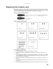
... these models, you need to select models only. OR - www.gateway.com Replacing the modem card This procedure applies to complete this task: 1 black (DVD drive) 2 black (hard drive kit) 2 black (keyboard cover) 1-3 black (keyboard) 4 black (LCD panel hinges) 4 black (palm rest - bottom) 2 chrome (modem card) To replace the modem card: 1 Complete the steps in "Preparing the notebook" on page 6. 2 Remove the DVD drive by following the instructions in "Replacing the DVD drive" on page 11. 3 If the notebook has IEEE 802.11 wireless networking...
... these models, you need to select models only. OR - www.gateway.com Replacing the modem card This procedure applies to complete this task: 1 black (DVD drive) 2 black (hard drive kit) 2 black (keyboard cover) 1-3 black (keyboard) 4 black (LCD panel hinges) 4 black (palm rest - bottom) 2 chrome (modem card) To replace the modem card: 1 Complete the steps in "Preparing the notebook" on page 6. 2 Remove the DVD drive by following the instructions in "Replacing the DVD drive" on page 11. 3 If the notebook has IEEE 802.11 wireless networking...

8511725 - Gateway Service Guide
Page 66
... tool 1 black (DVD drive) 2 black (hard drive kit) 2 black (keyboard cover) 1-3 black (keyboard) 4 black (LCD panel hinges) 4 black (palm rest - Phillips #0 screwdriver Screws removed during this task: Flat-blade driver - bottom) To replace the Bluetooth module: 1 Complete the steps in "Preparing the notebook" on page 6. 2 Remove the DVD drive by following the instructions in "Replacing the DVD drive" on page 11. 3 If the notebook has IEEE 802.11 wireless networking built in, unplug the antenna cables from the IEEE 802.11 wireless card by...
... tool 1 black (DVD drive) 2 black (hard drive kit) 2 black (keyboard cover) 1-3 black (keyboard) 4 black (LCD panel hinges) 4 black (palm rest - Phillips #0 screwdriver Screws removed during this task: Flat-blade driver - bottom) To replace the Bluetooth module: 1 Complete the steps in "Preparing the notebook" on page 6. 2 Remove the DVD drive by following the instructions in "Replacing the DVD drive" on page 11. 3 If the notebook has IEEE 802.11 wireless networking built in, unplug the antenna cables from the IEEE 802.11 wireless card by...

8511725 - Gateway Service Guide
Page 68
...this task: 1 black (DVD drive) 2 black (hard drive kit) 1 black (wireless card) Select models only 2 black (keyboard cover) 1-3 black (keyboard) 4 black (LCD panel hinges) 4 black (palm rest - bottom) 2 chrome (modem) Select models only 4 black (system board) To replace the system board: 1 Complete the steps in "Preparing the notebook" on page 6. 2 Remove the memory from the old system board and install it on the new system board by following the instructions in "Adding or replacing memory modules" on page 7. 64 Replacing Notebook Components Replacing the system board Tools you may...
...this task: 1 black (DVD drive) 2 black (hard drive kit) 1 black (wireless card) Select models only 2 black (keyboard cover) 1-3 black (keyboard) 4 black (LCD panel hinges) 4 black (palm rest - bottom) 2 chrome (modem) Select models only 4 black (system board) To replace the system board: 1 Complete the steps in "Preparing the notebook" on page 6. 2 Remove the memory from the old system board and install it on the new system board by following the instructions in "Adding or replacing memory modules" on page 7. 64 Replacing Notebook Components Replacing the system board Tools you may...

8511725 - Gateway Service Guide
Page 69
... notebook has IEEE 802.11 wireless networking built in, remove the IEEE 802.11 wireless card from the old system board and install it on the new system board by following the instructions in "Replacing the IEEE 802.11 wireless card" on page 22. 7 Remove the hard drive kit by following the instructions in "Replacing the hard drive" on page 26. 8 Remove the keyboard cover by following the instructions in "Replacing the keyboard cover" on page 29. 9 Remove the keyboard...
... notebook has IEEE 802.11 wireless networking built in, remove the IEEE 802.11 wireless card from the old system board and install it on the new system board by following the instructions in "Replacing the IEEE 802.11 wireless card" on page 22. 7 Remove the hard drive kit by following the instructions in "Replacing the hard drive" on page 26. 8 Remove the keyboard cover by following the instructions in "Replacing the keyboard cover" on page 29. 9 Remove the keyboard...
8511725 - Gateway Service Guide
Page 70
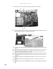
... by following the instructions in "Replacing the hard drive" on page 26. 23 Replace the DVD drive by following the instructions in "Replacing the DVD drive" on page 11. 24 Plug the antenna cables into the IEEE 802.11 wireless card, then replace the wireless bay cover. 66 Screw Screw Screw Screw 16 Turn the system board over and disconnect the external video board cable from the old system board and connect it to the notebook.
... by following the instructions in "Replacing the hard drive" on page 26. 23 Replace the DVD drive by following the instructions in "Replacing the DVD drive" on page 11. 24 Plug the antenna cables into the IEEE 802.11 wireless card, then replace the wireless bay cover. 66 Screw Screw Screw Screw 16 Turn the system board over and disconnect the external video board cable from the old system board and connect it to the notebook.
8511725 - Gateway Service Guide
Page 71
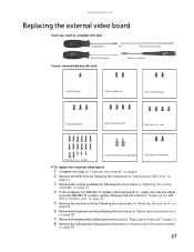
... hexnut (external video board) 2 black (external video board) To replace the external video board: 1 Complete the steps in "Preparing the notebook" on page 6. 2 Remove the DVD drive by following the instructions in "Replacing the DVD drive" on page 11. 3 Remove the cooling assembly by following the instructions in "Replacing the cooling assembly" on page 14. 4 If the notebook has IEEE 802.11 wireless networking built in, unplug the antenna cables from the IEEE 802.11 wireless card by...
... hexnut (external video board) 2 black (external video board) To replace the external video board: 1 Complete the steps in "Preparing the notebook" on page 6. 2 Remove the DVD drive by following the instructions in "Replacing the DVD drive" on page 11. 3 Remove the cooling assembly by following the instructions in "Replacing the cooling assembly" on page 14. 4 If the notebook has IEEE 802.11 wireless networking built in, unplug the antenna cables from the IEEE 802.11 wireless card by...
8511725 - Gateway Service Guide
Page 73
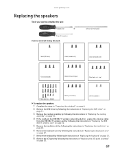
... tool 1 black (DVD drive) 2 black (hard drive kit) 2 black (keyboard cover) 1-3 black (keyboard) 4 black (LCD panel hinges) 4 black (palm rest - OR - bottom) 4 black (system board) 2 chrome (speakers) To replace the speakers: 1 Complete the steps in "Preparing the notebook" on page 6. 2 Remove the DVD drive by following the instructions in "Replacing the DVD drive" on page 11. 3 Remove the cooling assembly by following the instructions in "Replacing the cooling assembly" on page 14. 4 If the notebook has IEEE 802.11 wireless networking built...
... tool 1 black (DVD drive) 2 black (hard drive kit) 2 black (keyboard cover) 1-3 black (keyboard) 4 black (LCD panel hinges) 4 black (palm rest - OR - bottom) 4 black (system board) 2 chrome (speakers) To replace the speakers: 1 Complete the steps in "Preparing the notebook" on page 6. 2 Remove the DVD drive by following the instructions in "Replacing the DVD drive" on page 11. 3 Remove the cooling assembly by following the instructions in "Replacing the cooling assembly" on page 14. 4 If the notebook has IEEE 802.11 wireless networking built...
8512055 - Component Replacement Manual
Page 1
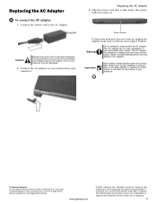
... connect the AC adapter: 1 Connect the power cord to disassemble the AC adapter. The AC adapter has no user-replaceable or user-serviceable parts inside. The AC adapter has dangerous voltages that can cause serious injury or death. www.gateway.com © 2007 Gateway, Inc. The power indicator turns on the bottom of the same type and voltage rating as the original cord or your notebook may be of your notebook's power...
... connect the AC adapter: 1 Connect the power cord to disassemble the AC adapter. The AC adapter has no user-replaceable or user-serviceable parts inside. The AC adapter has dangerous voltages that can cause serious injury or death. www.gateway.com © 2007 Gateway, Inc. The power indicator turns on the bottom of the same type and voltage rating as the original cord or your notebook may be of your notebook's power...
8512055 - Component Replacement Manual
Page 2
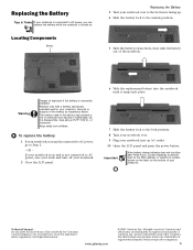
... facing up. 4 Slide the battery lock to Step 2. - Locating Components Battery Replacing the Battery 3 Turn your notebook into place. 7 Slide the battery lock to the lock position. 8 Turn your notebook over. 9 Plug your notebook over so the bottom is connected to AC power, go to the unlock position. 5 Slide the battery release latch, then slide the battery out of your notebook. Keep away from children. Technical Support See the label on...
... facing up. 4 Slide the battery lock to Step 2. - Locating Components Battery Replacing the Battery 3 Turn your notebook into place. 7 Slide the battery lock to the lock position. 8 Turn your notebook over. 9 Plug your notebook over so the bottom is connected to AC power, go to the unlock position. 5 Slide the battery release latch, then slide the battery out of your notebook. Keep away from children. Technical Support See the label on...
8512055 - Component Replacement Manual
Page 3
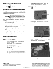
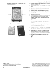
...." 2 Make sure that the DVD drive is empty. 3 Turn off your Reference Guide for Customer Care Information. www.gateway.com © 2007 Gateway, Inc. ESD can permanently damage electrostatic discharge-sensitive components in your notebook are extremely sensitive to dangerous electrical voltages and moving parts, turn off your notebook. 4 Disconnect the AC adapter, modem cable, and network cable. 5 Disconnect all peripheral devices and remove any PC Cards. 6 Turn your notebook...
...." 2 Make sure that the DVD drive is empty. 3 Turn off your Reference Guide for Customer Care Information. www.gateway.com © 2007 Gateway, Inc. ESD can permanently damage electrostatic discharge-sensitive components in your notebook are extremely sensitive to dangerous electrical voltages and moving parts, turn off your notebook. 4 Disconnect the AC adapter, modem cable, and network cable. 5 Disconnect all peripheral devices and remove any PC Cards. 6 Turn your notebook...
8512055 - Component Replacement Manual
Page 6
... valid boot devices appears. 18 Press the arrow keys to select the drive containing the Windows DVD, then press ENTER and follow the on-screen instructions. 19 After Windows is completely re-installed, use the software and driver recovery discs you will see a blank screen, insert the Windows DVD into your notebook, then replace the cover screws. 13 Insert the battery and turn your notebook over. 14 Connect the power adapter, modem cable, and network cable. 15 Turn on your Reference Guide for...
... valid boot devices appears. 18 Press the arrow keys to select the drive containing the Windows DVD, then press ENTER and follow the on-screen instructions. 19 After Windows is completely re-installed, use the software and driver recovery discs you will see a blank screen, insert the Windows DVD into your notebook, then replace the cover screws. 13 Insert the battery and turn your notebook over. 14 Connect the power adapter, modem cable, and network cable. 15 Turn on your Reference Guide for...
8512055 - Component Replacement Manual
Page 10
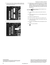
... cover screws. 13 Replace the keyboard screw. 14 Insert the battery, then turn your Reference Guide for Customer Care Information. All other countries. 8 If you are removing a memory module, gently press outward on the clip at a 30-degree angle and insert it into the empty memory slot. See your notebook over. 15 Connect the power adapter, the modem cable, and the network cable. 16 Reconnect all peripheral devices and replace...
... cover screws. 13 Replace the keyboard screw. 14 Insert the battery, then turn your Reference Guide for Customer Care Information. All other countries. 8 If you are removing a memory module, gently press outward on the clip at a 30-degree angle and insert it into the empty memory slot. See your notebook over. 15 Connect the power adapter, the modem cable, and the network cable. 16 Reconnect all peripheral devices and replace...
8512055 - Component Replacement Manual
Page 12
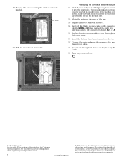
... the connector labelled MAIN or M, then reattach the light gray antenna cable to the connector labelled AUX or A. 15 Replace the wireless network bay cover, then tighten the cover screw. 16 Insert the battery, then turn your notebook over. 17 Connect the power adapter, the modem cable, and the network cable. 18 Reconnect all peripheral devices and replace any PC Cards. 19 Turn on the bottom of their respective companies...
... the connector labelled MAIN or M, then reattach the light gray antenna cable to the connector labelled AUX or A. 15 Replace the wireless network bay cover, then tighten the cover screw. 16 Insert the battery, then turn your notebook over. 17 Connect the power adapter, the modem cable, and the network cable. 18 Reconnect all peripheral devices and replace any PC Cards. 19 Turn on the bottom of their respective companies...


