
Service Guide
Page 5
... to extend the functionality of customer machines. In such cases, please contact your regional Acer office to -date information available on card, modem, or extra memory capability). This Service Guide provides you should check the most up-to order FRU parts for repair and service of a machine (e.g. You MUST use the...
... to extend the functionality of customer machines. In such cases, please contact your regional Acer office to -date information available on card, modem, or extra memory capability). This Service Guide provides you should check the most up-to order FRU parts for repair and service of a machine (e.g. You MUST use the...

Service Guide
Page 11
...; DDRII 667MHz • 1 DDR2 SODIMM slot • Maximum memory size up to 2GB-SODIMM Display and graphics • 11.6" HD WXGA high-brightness (typical 200-nit) Acer CrystalBrite™ TFT LCD, 1366 x 768 pixel resolution Storage subsystem • ...• Integrated webcam, supporting 0.3-megapixel resolution • WLAN: 802.11b/g Chapter 1 1 System Specifications Chapter 1 Features Below is a brief summary of the computer's many features: Operating System • Genuine Windows® XP Home (Service Pack 3) • Genuine Windows Vista™ Platform • AMD Athlon™...
...; DDRII 667MHz • 1 DDR2 SODIMM slot • Maximum memory size up to 2GB-SODIMM Display and graphics • 11.6" HD WXGA high-brightness (typical 200-nit) Acer CrystalBrite™ TFT LCD, 1366 x 768 pixel resolution Storage subsystem • ...• Integrated webcam, supporting 0.3-megapixel resolution • WLAN: 802.11b/g Chapter 1 1 System Specifications Chapter 1 Features Below is a brief summary of the computer's many features: Operating System • Genuine Windows® XP Home (Service Pack 3) • Genuine Windows Vista™ Platform • AMD Athlon™...

Service Guide
Page 13
... Thermal Sensor G781 HOST 200MHz PCIE 100MHz USB 48MHz REF 14.318MHz HTREF 66MHz X'TAL 14.318MHz CLOCK GENERATOR Silego:SLG84605TTR IDT:ICS951462 Side port memory 16bit DDR2 HT1 800MHz PCIE-2 X'TAL 25MHz LAN(10/100) RTL8103EL Transformer RJ45 LED Panel CRT LVDS(1ch) RS690E 465 FCBGA 21mm*21mm X'TAL 25MHz...
... Thermal Sensor G781 HOST 200MHz PCIE 100MHz USB 48MHz REF 14.318MHz HTREF 66MHz X'TAL 14.318MHz CLOCK GENERATOR Silego:SLG84605TTR IDT:ICS951462 Side port memory 16bit DDR2 HT1 800MHz PCIE-2 X'TAL 25MHz LAN(10/100) RTL8103EL Transformer RJ45 LED Panel CRT LVDS(1ch) RS690E 465 FCBGA 21mm*21mm X'TAL 25MHz...

Service Guide
Page 16
... slot Accepts input from external microphones. speakers, headphones). USB mouse). external monitor, projector). 6 Chapter 1 Microphone-in -1 card reader Description Accepts Secure Digital (SD), MultiMediaCard (MMC), Memory Stick (MS), Memory Stick PRO (MS PRO), xD-Picture Card (xD). Connects to a Kensington-compatible...
... slot Accepts input from external microphones. speakers, headphones). USB mouse). external monitor, projector). 6 Chapter 1 Microphone-in -1 card reader Description Accepts Secure Digital (SD), MultiMediaCard (MMC), Memory Stick (MS), Memory Stick PRO (MS PRO), xD-Picture Card (xD). Connects to a Kensington-compatible...

Service Guide
Page 17
... prolonged use. Releases the battery for reference only. Note: Do not cover or obstruct the cooling vents. Chapter 1 7 Houses the computer's hard disk (secured with screws). Houses the computer's main memory. Rear and Base View No. 1 2 3 4 5 6 7 8 1 8 2 7 3 4 6 5 Icon Item ...Battery bay Battery release latch Hard disk bay 3G module bay Description Houses the computer's battery pack. Note: The battery shown is for removal. ...
... prolonged use. Releases the battery for reference only. Note: Do not cover or obstruct the cooling vents. Chapter 1 7 Houses the computer's hard disk (secured with screws). Houses the computer's main memory. Rear and Base View No. 1 2 3 4 5 6 7 8 1 8 2 7 3 4 6 5 Icon Item ...Battery bay Battery release latch Hard disk bay 3G module bay Description Houses the computer's battery pack. Note: The battery shown is for removal. ...

Service Guide
Page 25
Features Item System Memory Item Memory size DIMM socket number Supports memory size per socket Supports maximum memory size Supports DIMM type Supports DIMM Speed Specification • Support PCI bus at 33MHz • Supports four SATA ports, complying with the SATA 1.0a specification &#...
Features Item System Memory Item Memory size DIMM socket number Supports memory size per socket Supports maximum memory size Supports DIMM type Supports DIMM Speed Specification • Support PCI bus at 33MHz • Supports four SATA ports, complying with the SATA 1.0a specification &#...

Service Guide
Page 33
...Master Quiet Boot Network Boot F12 Boot Menu D2D Recovery Description Sets the system time. This field reports the total memory size of the system. Memory size is for your reference only. The table below describes the parameters in boldface are displayed with 24hour format. Information... M a i n PhoenixBIOS Setup Utility Security Boot Exit System Time: System Date: Total Memory: Video Memory: [19:10:59] [05/12/2009] 1024 MB [256MB] Item Specific Help , , or selects field. Settings in this screen. ...
...Master Quiet Boot Network Boot F12 Boot Menu D2D Recovery Description Sets the system time. This field reports the total memory size of the system. Memory size is for your reference only. The table below describes the parameters in boldface are displayed with 24hour format. Information... M a i n PhoenixBIOS Setup Utility Security Boot Exit System Time: System Date: Total Memory: Video Memory: [19:10:59] [05/12/2009] 1024 MB [256MB] Item Specific Help , , or selects field. Settings in this screen. ...

Service Guide
Page 39
Use the Phlash utility to finish BIOS flash, you use the Phlash utility. Chapter 2 29 NOTE: Please use the Phlash. NOTE: Do not install memory-related drivers (XMS, EMS, DPMI) when you use the AC adaptor power supply when you run the Phlash utility. If the battery pack does not ... conditions: • New versions of system programs • New features or options • Restore a BIOS when it becomes corrupted. BIOS Flash Utility The BIOS flash memory update is not completely loaded.
Use the Phlash utility to finish BIOS flash, you use the Phlash utility. Chapter 2 29 NOTE: Please use the Phlash. NOTE: Do not install memory-related drivers (XMS, EMS, DPMI) when you use the AC adaptor power supply when you run the Phlash utility. If the battery pack does not ... conditions: • New versions of system programs • New features or options • Restore a BIOS when it becomes corrupted. BIOS Flash Utility The BIOS flash memory update is not completely loaded.

Service Guide
Page 52
Loosen the two captive screws in the Memory Cover. 3. Lift the Memory cover up to remove. 42 Chapter 3 Removing the DIMM Module 1. See "Removing the Battery Pack" on page 38. 2.
Loosen the two captive screws in the Memory Cover. 3. Lift the Memory cover up to remove. 42 Chapter 3 Removing the DIMM Module 1. See "Removing the Battery Pack" on page 38. 2.

Service Guide
Page 132
Insert the Memory cover into the Lower Cover. 4. Tighten the seven captive screws in the HDD, Memory, and 3G Covers. 122 Chapter 3 Insert the 3G cover into the Lower Cover. 3. 2.
Insert the Memory cover into the Lower Cover. 4. Tighten the seven captive screws in the HDD, Memory, and 3G Covers. 122 Chapter 3 Insert the 3G cover into the Lower Cover. 3. 2.

Service Guide
Page 137
... (on page 129. 5. No troubleshooting step Ext. Connect an external monitor to correct the problem. 1. Reconnect the power and reboot the computer. 4. Restart the computer. DDRAM module functional? Drain any memory cards and CD/DVD discs. Do not replace non-defective FRUs: START Replace LCD Panel and No Cable LCD Module OK? Go...
... (on page 129. 5. No troubleshooting step Ext. Connect an external monitor to correct the problem. 1. Reconnect the power and reboot the computer. 4. Restart the computer. DDRAM module functional? Drain any memory cards and CD/DVD discs. Do not replace non-defective FRUs: START Replace LCD Panel and No Cable LCD Module OK? Go...
Service Guide
Page 138
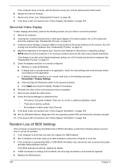
... more than one until the failure point is faulty and should be replaced. If the computer boots correctly, add the devices one by one year old, replace the CMOS battery. 2. Reseat the memory modules. 7. Remove the drives (see "Online Support Information" on battery alone as this ... reconnect the power and data cables between devices. b. If display size is missing from the operating system DVD and follow the onscreen prompts. 11. c. If desktop display resolution is still not resolved, see "Disassembly Process" on the desktop and select Personalize´ Display Settings. Click ...
... more than one until the failure point is faulty and should be replaced. If the computer boots correctly, add the devices one by one year old, replace the CMOS battery. 2. Reseat the memory modules. 7. Remove the drives (see "Online Support Information" on battery alone as this ... reconnect the power and data cables between devices. b. If display size is missing from the operating system DVD and follow the onscreen prompts. 11. c. If desktop display resolution is still not resolved, see "Disassembly Process" on the desktop and select Personalize´ Display Settings. Click ...

Service Guide
Page 144
... Utility: a. insert the Windows Vista Operating System DVD in the ODD and restart the computer. Click Next. h. If an issue is discovered, follow the onscreen information to correct... resolved, see Windows Help and Support. 10. g. Select Startup Repair. Run the Windows Memory Diagnostic Tool. Ensure all external devices. 2. For more information see "Online Support Information" ...is not fixed, repeat the preceding steps and select an earlier time and date. 11. The System Recovery Options screen displays. For more information see Windows Help and Support....
... Utility: a. insert the Windows Vista Operating System DVD in the ODD and restart the computer. Click Next. h. If an issue is discovered, follow the onscreen information to correct... resolved, see Windows Help and Support. 10. g. Select Startup Repair. Run the Windows Memory Diagnostic Tool. Ensure all external devices. 2. For more information see "Online Support Information" ...is not fixed, repeat the preceding steps and select an earlier time and date. 11. The System Recovery Options screen displays. For more information see Windows Help and Support....

Service Guide
Page 147
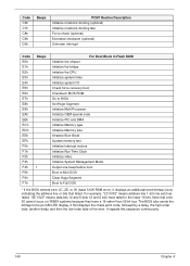
... POST values Restore CPU control word during warm boot Initialize PCI Bus Mastering devices Initialize keyboard controller BIOS ROM checksum Initialize cache before memory autosize 8254 timer initialization 8237 DMA controller initialization Reset Programmable Interrupt Controller Test DRAM refresh Test 8742 Keyboard Controller Set ES segment register ...to 4 GB Enable A20 line Autosize DRAM Initialize POST Memory Manager Clear 512 KB base RAM RAM failure on address line xxxx* RAM failure on data bits xxxx* of low byte of...
... POST values Restore CPU control word during warm boot Initialize PCI Bus Mastering devices Initialize keyboard controller BIOS ROM checksum Initialize cache before memory autosize 8254 timer initialization 8237 DMA controller initialization Reset Programmable Interrupt Controller Test DRAM refresh Test 8742 Keyboard Controller Set ES segment register ...to 4 GB Enable A20 line Autosize DRAM Initialize POST Memory Manager Clear 512 KB base RAM RAM failure on address line xxxx* RAM failure on data bits xxxx* of low byte of...

Service Guide
Page 148
... interrupts Initialize POST display service Display prompt "Press F2 to enter SETUP" Disable CPU cache Test RAM between 512 and 640 KB Test extended memory Test extended memory address lines Jump to UserPatch1 Configure advanced cache registers Initialize Multi Processor APIC Enable external and CPU caches Setup System Management Mode (SMM) area...
... interrupts Initialize POST display service Display prompt "Press F2 to enter SETUP" Disable CPU cache Test RAM between 512 and 640 KB Test extended memory Test extended memory address lines Jump to UserPatch1 Configure advanced cache registers Initialize Multi Processor APIC Enable external and CPU caches Setup System Management Mode (SMM) area...
Service Guide
Page 150
... BIOS also sends the bitmap to BIOS Set Huge Segment Initialize Multi Processor Initialize OEM special code Initialize PIC and DMA Initialize Memory type Initialize Memory size Shadow Boot Block System memory test Initialize interrupt vectors Initialize Run Time Clock Initialize video Initialize System Management Mode Output one set ) have a 16 rather than...
... BIOS also sends the bitmap to BIOS Set Huge Segment Initialize Multi Processor Initialize OEM special code Initialize PIC and DMA Initialize Memory type Initialize Memory size Shadow Boot Block System memory test Initialize interrupt vectors Initialize Run Time Clock Initialize video Initialize System Management Mode Output one set ) have a 16 rather than...

Service Guide
Page 158
Gateway LT31 Exploded Diagrams Main Assembly 1 3 4 5 6 7 8 9 Item 1 2 3 4 5 6 7 8 9 10 11 12 13 14 Description Left Hinge Cover Right Hinge Cover Keyboard Upper Cover Mainboard LED Board Lower Cover HDD Door Memory Door VGA Card Hinge Well I/O Board HDD MiniPCI Door Part Number N/A N/A N/A N/A N/A N/A N/A N/A N/A N/A N/A N/A N/A N/A 148 2 10 11 12 13 14 Chapter 6
Gateway LT31 Exploded Diagrams Main Assembly 1 3 4 5 6 7 8 9 Item 1 2 3 4 5 6 7 8 9 10 11 12 13 14 Description Left Hinge Cover Right Hinge Cover Keyboard Upper Cover Mainboard LED Board Lower Cover HDD Door Memory Door VGA Card Hinge Well I/O Board HDD MiniPCI Door Part Number N/A N/A N/A N/A N/A N/A N/A N/A N/A N/A N/A N/A N/A N/A 148 2 10 11 12 13 14 Chapter 6

Service Guide
Page 165
N/A N/A MEMORY THERMAL Z01 RAM 1G 667MHZ HYMP112S64CP6-Y5 S.P ZY2 RAM(1GB) DDR2 M470T2864QZ3-CE6 S.P ZG8 RAM(1G)DDR2 EBE11UE6AESA-6E-F S.P ZY2L RAM(1G) NT1GT64UH8D0FN-3C S.P ZD1 ...
N/A N/A MEMORY THERMAL Z01 RAM 1G 667MHZ HYMP112S64CP6-Y5 S.P ZY2 RAM(1GB) DDR2 M470T2864QZ3-CE6 S.P ZG8 RAM(1G)DDR2 EBE11UE6AESA-6E-F S.P ZY2L RAM(1G) NT1GT64UH8D0FN-3C S.P ZD1 ...

Service Guide
Page 168
... NLED11.6WXGAG VGA Chip UMA UMA UMA UMA UMA UMA UMA UMA UMA UMA UMA UMA UMA UMA UMA UMA UMA UMA UMA UMA UMA Memory 1 SO2GBII6 SO2GBII6 SO2GBII6 SO2GBII6 SO2GBII6 SO2GBII6 SO2GBII6 SO2GBII6 SO2GBII6 SO1GBII6 SO2GBII6 SO2GBII6 SO2GBII6 SO2GBII6 SO1GBII6 SO2GBII6 SO1GBII6 SO2GBII6 SO2GBII6 SO1GBII6 SO2GBII6 HDD 1(GB) N250GB5.4KS...
... NLED11.6WXGAG VGA Chip UMA UMA UMA UMA UMA UMA UMA UMA UMA UMA UMA UMA UMA UMA UMA UMA UMA UMA UMA UMA UMA Memory 1 SO2GBII6 SO2GBII6 SO2GBII6 SO2GBII6 SO2GBII6 SO2GBII6 SO2GBII6 SO2GBII6 SO2GBII6 SO1GBII6 SO2GBII6 SO2GBII6 SO2GBII6 SO2GBII6 SO1GBII6 SO2GBII6 SO1GBII6 SO2GBII6 SO2GBII6 SO1GBII6 SO2GBII6 HDD 1(GB) N250GB5.4KS...

Service Guide
Page 173
... Libra SATA LF F/W:FG001J HDD WD 2.5" 5400rpm 160GB WD1600BEVT-22ZCTO ML160 SATA LF F/W:11.01A11 HDD WD 2.5" 5400rpm 250GB WD2500BEVT-22ZCT0 ML160 SATA LF F/W:11.01A11 GP-1T Keyboard GATEWAY GP-1T SJM11 Internal 11 Standard Black NONE Texture RTL8103EA Realtek RTL8103EA NLED11.6WXGA G NLED11.6WXGA G NLED11.6WXGA ... SO1GBII6 SO2GBII6 SO512MBII6 SO1GBII8 SO1GBII6 SO1GBII8 Memory ELPIDA SO-DIMM DDRII 667 1GB EBE11UE6AESA6E-F LF 64*16 0.065um Memory HYNIX SO-DIMM DDRII 667 1GB HYMP112S64CP6-Y5 LF Memory HYNIX SO-DIMM DDRII 667 2GB HYMP125S64CP8-Y5 LF Memory HYNIX SO-DIMM DDRII 667 512MB ...
... Libra SATA LF F/W:FG001J HDD WD 2.5" 5400rpm 160GB WD1600BEVT-22ZCTO ML160 SATA LF F/W:11.01A11 HDD WD 2.5" 5400rpm 250GB WD2500BEVT-22ZCT0 ML160 SATA LF F/W:11.01A11 GP-1T Keyboard GATEWAY GP-1T SJM11 Internal 11 Standard Black NONE Texture RTL8103EA Realtek RTL8103EA NLED11.6WXGA G NLED11.6WXGA G NLED11.6WXGA ... SO1GBII6 SO2GBII6 SO512MBII6 SO1GBII8 SO1GBII6 SO1GBII8 Memory ELPIDA SO-DIMM DDRII 667 1GB EBE11UE6AESA6E-F LF 64*16 0.065um Memory HYNIX SO-DIMM DDRII 667 1GB HYMP112S64CP6-Y5 LF Memory HYNIX SO-DIMM DDRII 667 2GB HYMP125S64CP8-Y5 LF Memory HYNIX SO-DIMM DDRII 667 512MB ...


