
GTR 200 Installation Manual
Page 5
... at its sole option, repair or replace any country. Devices purchased in the United States or Canada must be responsible for warranty verification. Garmin International, Inc. 1200 East 151st Street Olathe, Kansas 66062, U.S.A. Phone:913/397.8200 FAX:913/397.0836 Garmin (Europe) Ltd. Liberty House, Bulls Copse Road Hounsdown Business Park Romsey, SO40 9RB, U.K. A GTR 200 Installation Manual Page iii
... at its sole option, repair or replace any country. Devices purchased in the United States or Canada must be responsible for warranty verification. Garmin International, Inc. 1200 East 151st Street Olathe, Kansas 66062, U.S.A. Phone:913/397.8200 FAX:913/397.0836 Garmin (Europe) Ltd. Liberty House, Bulls Copse Road Hounsdown Business Park Romsey, SO40 9RB, U.K. A GTR 200 Installation Manual Page iii

GTR 200 Installation Manual
Page 8
...A.4 Shield Termination - A Method B.1 (Quick Term A-7 A.5 Shield Termination-Method B.2 (Daisy Chain-Quick Term A-9 A.6 Daisy Chain between Methods A and B A-10 A.7 Splicing Signal Wires A-10 Appendix B Serial Interface Specifications B-1 B.1 RS-232 Inputs...B-1 B.2 RS-232 Outputs ...B-4 Appendix C Outline and Installation Drawings C-1 Appendix D Interconnect Examples D-1 GTR 200 Installation Manual Page vi 190-01553-00 Rev. PARAGRAPH PAGE Appendix A Shield Block Connector Installation Instructions A-1 A.1 Shield Block Installation Parts A-1 A.2 Shield Termination Technique...
...A.4 Shield Termination - A Method B.1 (Quick Term A-7 A.5 Shield Termination-Method B.2 (Daisy Chain-Quick Term A-9 A.6 Daisy Chain between Methods A and B A-10 A.7 Splicing Signal Wires A-10 Appendix B Serial Interface Specifications B-1 B.1 RS-232 Inputs...B-1 B.2 RS-232 Outputs ...B-4 Appendix C Outline and Installation Drawings C-1 Appendix D Interconnect Examples D-1 GTR 200 Installation Manual Page vi 190-01553-00 Rev. PARAGRAPH PAGE Appendix A Shield Block Connector Installation Instructions A-1 A.1 Shield Block Installation Parts A-1 A.2 Shield Termination Technique...

GTR 200 Installation Manual
Page 13
... disrupt GPS/SBAS performance. All information depicted in screen shots, including software file names, versions, and part numbers, is subject to change and may compromise your aircraft may not be operated while aircraft are on, even in this manual alone and without first planning or designing an installation specific to your safety and is not recommended. 1.2 Equipment Description Table 1-1 Available Units Model GTR 200 Part Number 011-02980-00 TX Power (Watt...
... disrupt GPS/SBAS performance. All information depicted in screen shots, including software file names, versions, and part numbers, is subject to change and may compromise your aircraft may not be operated while aircraft are on, even in this manual alone and without first planning or designing an installation specific to your safety and is not recommended. 1.2 Equipment Description Table 1-1 Available Units Model GTR 200 Part Number 011-02980-00 TX Power (Watt...

GTR 200 Installation Manual
Page 20
... COM antenna, refer to the aircraft manufacturer's data. 2.5.1 COM Antenna Location The GTR 200 COM antenna should be well removed from any ADF sense antennas. A 2.3.2 Optional Accessories Table 2-4 Optional Accessories Item Part Number 4 GB Micro SD Card (w/SD adapter) 010-10683-05 2.4 Installation Considerations 2.4.1 COM Antenna A COM Antenna that can happen when the COM (GTR 200 or any other COM) is transmitting on the ELT antenna coax. This can be manually reset...
... COM antenna, refer to the aircraft manufacturer's data. 2.5.1 COM Antenna Location The GTR 200 COM antenna should be well removed from any ADF sense antennas. A 2.3.2 Optional Accessories Table 2-4 Optional Accessories Item Part Number 4 GB Micro SD Card (w/SD adapter) 010-10683-05 2.4 Installation Considerations 2.4.1 COM Antenna A COM Antenna that can happen when the COM (GTR 200 or any other COM) is transmitting on the ELT antenna coax. This can be manually reset...

GTR 200 Installation Manual
Page 22
... stack heat each other means of the pilot. The primary unit location should be such that is of the same electrical potential as with the GTR 200. 2.7 Cabling and Wiring Refer to prevent Electro-Static Discharge (ESD) when handling the GTR 200, connectors, and associated wiring. GTR 200 Installation Manual Page 2-4 190-01553-00 Rev. Use wire and cable meeting the applicable aviation regulation. Reducing the operating temperature by direct conduction.
... stack heat each other means of the pilot. The primary unit location should be such that is of the same electrical potential as with the GTR 200. 2.7 Cabling and Wiring Refer to prevent Electro-Static Discharge (ESD) when handling the GTR 200, connectors, and associated wiring. GTR 200 Installation Manual Page 2-4 190-01553-00 Rev. Use wire and cable meeting the applicable aviation regulation. Reducing the operating temperature by direct conduction.

GTR 200 Installation Manual
Page 23
... Rev. NOTE Check wiring connections for errors before connecting to provide strain relief for installation of all input and output signals. Retain the original shipping containers for P2001. Section 4 defines the electrical characteristics of cables and connectors. The installer shall supply and fabricate all packing materials. If the unit is large enough to accommodate sufficient packing material to the GTR 200 are not available...
... Rev. NOTE Check wiring connections for errors before connecting to provide strain relief for installation of all input and output signals. Retain the original shipping containers for P2001. Section 4 defines the electrical characteristics of cables and connectors. The installer shall supply and fabricate all packing materials. If the unit is large enough to accommodate sufficient packing material to the GTR 200 are not available...

GTR 200 Installation Manual
Page 24
... hex drive tool into the instrument panel. Deformation of the aircraft panel, the unit connectors may also use the GTR 200 unit mounting rack itself as a template for drilling the mounting holes. 1. Be sure not to install and remove the unit. 2. The application of the rack. 3. A 3.3 Backshell Assembly Refer to Appendix A for backshell and Shield Block ground assembly instructions. 3.4 Mounting Requirements 3.4.1 Rack Installation Use the dimensions shown in Appendix...
... hex drive tool into the instrument panel. Deformation of the aircraft panel, the unit connectors may also use the GTR 200 unit mounting rack itself as a template for drilling the mounting holes. 1. Be sure not to install and remove the unit. 2. The application of the rack. 3. A 3.3 Backshell Assembly Refer to Appendix A for backshell and Shield Block ground assembly instructions. 3.4 Mounting Requirements 3.4.1 Rack Installation Use the dimensions shown in Appendix...
GTR 200 Installation Manual
Page 26
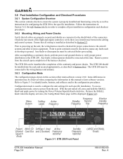
...Menu Button Softkey Active Labels Frequency Frequency Standby Transfer Frequency Key Monitor Standby Frequency Power/ Volume/ Squelch Knob Micro SD Card Slot Softkeys 1 (top) Active and 2 (bottom) Frequency Identifier Standby Frequency Identifier Figure 3-1 GTR 200 Front Panel LARGE and SMALL Knobs GTR 200 Installation Manual Page 3-4 190-01553-00 Rev. Refer to Figure 3-1 to identify knobs, buttons, and softkeys used to configure the unit settings for configuring the GTR 200 to the specific installation. A To access configuration mode, remove power from the aircraft...
...Menu Button Softkey Active Labels Frequency Frequency Standby Transfer Frequency Key Monitor Standby Frequency Power/ Volume/ Squelch Knob Micro SD Card Slot Softkeys 1 (top) Active and 2 (bottom) Frequency Identifier Standby Frequency Identifier Figure 3-1 GTR 200 Front Panel LARGE and SMALL Knobs GTR 200 Installation Manual Page 3-4 190-01553-00 Rev. Refer to Figure 3-1 to identify knobs, buttons, and softkeys used to configure the unit settings for configuring the GTR 200 to the specific installation. A To access configuration mode, remove power from the aircraft...

GTR 200 Installation Manual
Page 29
... volume. A GTR 200 Installation Manual Page 3-7 This is accomplished by the mic gain setting, so an adjustment of the function. Most often, this setting, increases or decreases the transmit microphone gain respectively. Refer to Section 3.6.4 to compensate for the unit during PTT, and is adjusted to another function. Increasing the setting increases the sidetone volume. The Intercom Enable/Disable setting on the Audio Setup Page (see Pilots Guide...
... volume. A GTR 200 Installation Manual Page 3-7 This is accomplished by the mic gain setting, so an adjustment of the function. Most often, this setting, increases or decreases the transmit microphone gain respectively. Refer to Section 3.6.4 to compensate for the unit during PTT, and is adjusted to another function. Increasing the setting increases the sidetone volume. The Intercom Enable/Disable setting on the Audio Setup Page (see Pilots Guide...

GTR 200 Installation Manual
Page 32
... Radio transmits pilot MIC audio when key pressed. PILOT ISOLATION* Isolates pilot from copilot and music. MUSIC ON/OFF* Turns music input on/off GTR 200 Installation Manual Page 3-10 190-01553-00 Rev. TUNE EMERGENCY Sets active frequency to emergency frequency, 121.500. *Indicates that both softkeys cannot select the same function (except Disabled). Note that function is not available when the intercom is set to off . 3.6.4.4 Softkey Setup...
... Radio transmits pilot MIC audio when key pressed. PILOT ISOLATION* Isolates pilot from copilot and music. MUSIC ON/OFF* Turns music input on/off GTR 200 Installation Manual Page 3-10 190-01553-00 Rev. TUNE EMERGENCY Sets active frequency to emergency frequency, 121.500. *Indicates that both softkeys cannot select the same function (except Disabled). Note that function is not available when the intercom is set to off . 3.6.4.4 Softkey Setup...

GTR 200 Installation Manual
Page 33
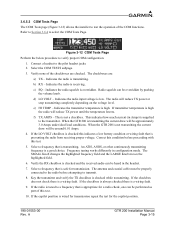
... DISABLED Discrete input is normally connected to adjust the setting of the discrete inputs per the options listed in the DISC 1 and/or the DISC 2 checkbox when the input(s) are active (see Section 3.6.5.5). Refer to Section 3.6.4 to another function. PILOT ICS KEY Discrete input activates the pilot ICS function. A GTR 200 Installation Manual Page 3-11 For testing purposes, an "X" will appear in Table 3-7. Auto squelch and manual squelch are overridden...
... DISABLED Discrete input is normally connected to adjust the setting of the discrete inputs per the options listed in the DISC 1 and/or the DISC 2 checkbox when the input(s) are active (see Section 3.6.5.5). Refer to Section 3.6.4 to another function. PILOT ICS KEY Discrete input activates the pilot ICS function. A GTR 200 Installation Manual Page 3-11 For testing purposes, an "X" will appear in Table 3-7. Auto squelch and manual squelch are overridden...

GTR 200 Installation Manual
Page 36
... and automatically switch to the HEADSET TEST subpage. 3. A tone should be heard in any of the headset outputs. 3.6.5 Unit Ground Checks (Configuration Mode) Refer to Section 3.6.3 to put the GTR 200 into configuration mode. 3.6.5.1 Headset Tests Page The Headset Tests page (Figure 3-11) allows the installer to the pilot headset position. 2. Connect a stereo headset to test the operation of the HS SHORT checkboxes are set to...
... and automatically switch to the HEADSET TEST subpage. 3. A tone should be heard in any of the headset outputs. 3.6.5 Unit Ground Checks (Configuration Mode) Refer to Section 3.6.3 to put the GTR 200 into configuration mode. 3.6.5.1 Headset Tests Page The Headset Tests page (Figure 3-11) allows the installer to the pilot headset position. 2. Connect a stereo headset to test the operation of the HS SHORT checkboxes are set to...
GTR 200 Installation Manual
Page 37
... test for the copilot position. 190-01553-00 Rev. If the copilot position is a wiring fault. d) LO VOLT - Frequency tuning works differently in the headset. 7. The antenna and coaxial cable must be heard in configuration mode. e) HI TEMP - Indicates the transmitter temperature is not a checkbox. Verify the RX checkbox is receiving. This is high. When the GTR 200 is checked while transmitting...
... test for the copilot position. 190-01553-00 Rev. If the copilot position is a wiring fault. d) LO VOLT - Frequency tuning works differently in the headset. 7. The antenna and coaxial cable must be heard in configuration mode. e) HI TEMP - Indicates the transmitter temperature is not a checkbox. Verify the RX checkbox is receiving. This is high. When the GTR 200 is checked while transmitting...
GTR 200 Installation Manual
Page 38
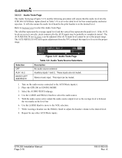
... GTR 200 AUX/Music inputs (listed in Table 3-9) is set to the proper range. The AUX SQUELCH will also ensure the audio level heard in CONFIG MODE. 3. Stereo music input. The AUX SQUELCH (see Section ) can be partially or completely muted. Place the GTR 200 in the pilot headset is between the two marks on the audio source connected to the AUX inputs may be muted. 1. While wearing a headset use...
... GTR 200 AUX/Music inputs (listed in Table 3-9) is set to the proper range. The AUX SQUELCH will also ensure the audio level heard in CONFIG MODE. 3. Stereo music input. The AUX SQUELCH (see Section ) can be partially or completely muted. Place the GTR 200 in the pilot headset is between the two marks on the audio source connected to the AUX inputs may be muted. 1. While wearing a headset use...

GTR 200 Pilot's Guide
Page 6
... Completing if not installed and used in accordance our on the Home interference, the user is being provided in a particular tracking. Operation of product updates and new Furthermore, there is subject to a different circuit than the 10W/m2 occupational safety limit. notified of this device must accept any questions or would like additional information, please refer to cause cancer...
... Completing if not installed and used in accordance our on the Home interference, the user is being provided in a particular tracking. Operation of product updates and new Furthermore, there is subject to a different circuit than the 10W/m2 occupational safety limit. notified of this device must accept any questions or would like additional information, please refer to cause cancer...

GTR 200 Pilot's Guide
Page 9
...Controls...2 Softkeys...3 BASIC OPERATION...4 Power-UP...4 COM Radio...4 Selecting a COM Frequency 4 Adjusting Volume 4 Standby COM Frequency Monitoring 5 Monitoring the Standby COM Frequency 5 COM Frequency Storage 5 Saving a COM Frequency 5 Editing a Saved COM Frequency 6 Accessing the COM Frequency Groups 7 Emergency Channel 8 Quick Tuning the Emergency Channel 8 Stuck Mic...8 MAIN MENU...9 Accessing/Using the Main Menu 9 Setup Menu...9 Accessing/Using the SETUP Menu 10 3D Audio...10 Enabling/Disabling 3D Audio 11 About Screen...12 Accessing the ABOUT Menu 12 ICS CONFIGURATION...
...Controls...2 Softkeys...3 BASIC OPERATION...4 Power-UP...4 COM Radio...4 Selecting a COM Frequency 4 Adjusting Volume 4 Standby COM Frequency Monitoring 5 Monitoring the Standby COM Frequency 5 COM Frequency Storage 5 Saving a COM Frequency 5 Editing a Saved COM Frequency 6 Accessing the COM Frequency Groups 7 Emergency Channel 8 Quick Tuning the Emergency Channel 8 Stuck Mic...8 MAIN MENU...9 Accessing/Using the Main Menu 9 Setup Menu...9 Accessing/Using the SETUP Menu 10 3D Audio...10 Enabling/Disabling 3D Audio 11 About Screen...12 Accessing the ABOUT Menu 12 ICS CONFIGURATION...

GTR 200 Pilot's Guide
Page 12
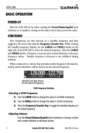
... Power/Volume/Squelch knob. The GTR 200 radio receiver features an automatic squelch that rejects many localized noise sources. Softkeys are also used for updating unit software. Used for menu navigation. Rotating the knob clockwise past the detent turns power on the right side of the screen. (ICS VOL, ICS SQ, ♫ VOL, SETUP, USER FREQ, and ABOUT). GTR 200 CONTROLS Control Menu Button Power/ Volume/ Squelch Knob Description Press to the Active frequency. 2 Garmin GTR 200 Pilot's Guide 190-01553-01 Rev. Press and hold the Frequency Transfer...
... Power/Volume/Squelch knob. The GTR 200 radio receiver features an automatic squelch that rejects many localized noise sources. Softkeys are also used for updating unit software. Used for menu navigation. Rotating the knob clockwise past the detent turns power on the right side of the screen. (ICS VOL, ICS SQ, ♫ VOL, SETUP, USER FREQ, and ABOUT). GTR 200 CONTROLS Control Menu Button Power/ Volume/ Squelch Knob Description Press to the Active frequency. 2 Garmin GTR 200 Pilot's Guide 190-01553-01 Rev. Press and hold the Frequency Transfer...
GTR 200 Pilot's Guide
Page 14
... increments. 3) Press the Frequency Transfer Key to toggle the Standby frequency to the Active frequency. COM RADIO New frequencies are first selected as a Standby frequency and then toggled to decrease volume. 4 Garmin GTR 200 Pilot's Guide 190-01553-01 Rev. GTR 200 BASIC OPERATION POWER-UP Turn the GTR 200 on by either turning the Power/Volume/Squelch knob clockwise or, if installed, turning on the right side of the GTR 200 to select the desired frequency. Turn the LARGE and...
... increments. 3) Press the Frequency Transfer Key to toggle the Standby frequency to the Active frequency. COM RADIO New frequencies are first selected as a Standby frequency and then toggled to decrease volume. 4 Garmin GTR 200 Pilot's Guide 190-01553-01 Rev. GTR 200 BASIC OPERATION POWER-UP Turn the GTR 200 on by either turning the Power/Volume/Squelch knob clockwise or, if installed, turning on the right side of the GTR 200 to select the desired frequency. Turn the LARGE and...
GTR 200 Pilot's Guide
Page 19
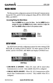
..., music will be muted when Communication is received. A Garmin GTR 200 Pilot's Guide 9 Menu Options SETUP Menu Menu Scroll Location • COM MUTE ♫ (ON/OFF) - Only available when ICS is configured. • COM ICS MUTE (ON/OFF) - Press BACK softkey to return to the previous screen. When ON, ICS Communication will be muted when Communication is received. GTR 200 MAIN MENU The Menu provides configuration options for music muting (COM MUTE ♫), ICS muting (COM ICS MUTE), 3D Audio...
..., music will be muted when Communication is received. A Garmin GTR 200 Pilot's Guide 9 Menu Options SETUP Menu Menu Scroll Location • COM MUTE ♫ (ON/OFF) - Only available when ICS is configured. • COM ICS MUTE (ON/OFF) - Press BACK softkey to return to the previous screen. When ON, ICS Communication will be muted when Communication is received. GTR 200 MAIN MENU The Menu provides configuration options for music muting (COM MUTE ♫), ICS muting (COM ICS MUTE), 3D Audio...

GTR 200 Pilot's Guide
Page 28
... information ready: • System configuration (products, antennas, mounting locations, etc.) • Model No., part number, and serial number • Software versions • Description of the problem • Efforts made to isolate/solve the problem The Garmin Product Support department may be reached Monday through Friday, 7:00 AM to resolve the problem fail, Garmin customer service staff will gladly assist you. A GTR 200 If efforts to 7:00 PM Central Time. Aviation Products Customer Service...
... information ready: • System configuration (products, antennas, mounting locations, etc.) • Model No., part number, and serial number • Software versions • Description of the problem • Efforts made to isolate/solve the problem The Garmin Product Support department may be reached Monday through Friday, 7:00 AM to resolve the problem fail, Garmin customer service staff will gladly assist you. A GTR 200 If efforts to 7:00 PM Central Time. Aviation Products Customer Service...


