Manual/User Guide
Page 5
...of the drives and explains in detail how to read this manual. CHAPTER 5 Interface This chapter describes the interface specifications of the disk drive. CHAPTER 4 Theory of Device Operation This chapter describes the operation theory of the MHT Series, 2.5-inch hard disk drives. Acronyms ...incorporate the drives into user systems. This manual assumes that the reader has a basic knowledge of hard disk drives and their implementations in which they operate. These drives have a built-in this manual. Preface This manual describes MHT2080AT/ MHT2060AT/ MHT2040AT/ MHT2030AT/ MHT2020AT models...
...of the drives and explains in detail how to read this manual. CHAPTER 5 Interface This chapter describes the interface specifications of the disk drive. CHAPTER 4 Theory of Device Operation This chapter describes the operation theory of the MHT Series, 2.5-inch hard disk drives. Acronyms ...incorporate the drives into user systems. This manual assumes that the reader has a basic knowledge of hard disk drives and their implementations in which they operate. These drives have a built-in this manual. Preface This manual describes MHT2080AT/ MHT2060AT/ MHT2040AT/ MHT2030AT/ MHT2020AT models...
Manual/User Guide
Page 11
Manual Organization MHT2080AT, MHT2060AT, MHT2040AT MHT2030AT, MHT2020AT DISK DRIVES PRODUCT MANUAL (C141-E192) • Device Overview • Device Configuration • Installation Conditions • Theory of Device Operation • Interface • Operations MHT2080AT, MHT2060AT, MHT2040AT MHT2030AT, MHT2020AT DISK DRIVES MAINTENANCE MANUAL (C141-F063) • Maintenance and Diagnosis • Removal and Replacement Procedure C141-E192-02EN vii
Manual Organization MHT2080AT, MHT2060AT, MHT2040AT MHT2030AT, MHT2020AT DISK DRIVES PRODUCT MANUAL (C141-E192) • Device Overview • Device Configuration • Installation Conditions • Theory of Device Operation • Interface • Operations MHT2080AT, MHT2060AT, MHT2040AT MHT2030AT, MHT2020AT DISK DRIVES MAINTENANCE MANUAL (C141-F063) • Maintenance and Diagnosis • Removal and Replacement Procedure C141-E192-02EN vii

Manual/User Guide
Page 15
... control circuit 4-13 4.7.2 Data-surface servo format 4-16 4.7.3 Servo frame format 4-18 4.7.4 Actuator motor control 4-19 4.7.5 Spindle motor control 4-20 CHAPTER 5 Interface 5-1 5.1 Physical Interface 5-2 5.1.1 Interface signals 5-2 5.1.2 Signal assignment on the connector 5-3 5.2 Logical Interface 5-6 5.2.1 I/O registers 5-7 5.2.2 Command block registers 5-8 5.2.3 Control block registers 5-13 5.3 Host Commands 5-14 5.3.1 Command code and parameters 5-14 5.3.2 Command descriptions 5-18 5.3.3 Error posting...
... control circuit 4-13 4.7.2 Data-surface servo format 4-16 4.7.3 Servo frame format 4-18 4.7.4 Actuator motor control 4-19 4.7.5 Spindle motor control 4-20 CHAPTER 5 Interface 5-1 5.1 Physical Interface 5-2 5.1.1 Interface signals 5-2 5.1.2 Signal assignment on the connector 5-3 5.2 Logical Interface 5-6 5.2.1 I/O registers 5-7 5.2.2 Command block registers 5-8 5.2.3 Control block registers 5-13 5.3 Host Commands 5-14 5.3.1 Command code and parameters 5-14 5.3.2 Command descriptions 5-18 5.3.3 Error posting...
Manual/User Guide
Page 18
... V when power is turned off 1-6 Figure 1.2 Current fluctuation (Typ.) at +5 V when power is turned on 1-8 Figure 2.1 Disk drive outerview 2-2 Figure 2.2 1 drive system configuration 2-3 Figure 2.3 2 drives configuration 2-4 Figure 3.1 Dimensions 3-2 Figure 3.2 Orientation 3-3 Figure 3.3 Mounting frame structure 3-4 Figure 3.4 Location of breather 3-5 Figure 3.5 Surface ...sector servo configuration on disk surface 4-17 Servo frame format 4-18 Figure 5.1 Interface signals 5-2 Figure 5.2 Execution example of READ MULTIPLE command 5-21 Figure 5.3 Read Sector(s) command protocol 5-111 ...
... V when power is turned off 1-6 Figure 1.2 Current fluctuation (Typ.) at +5 V when power is turned on 1-8 Figure 2.1 Disk drive outerview 2-2 Figure 2.2 1 drive system configuration 2-3 Figure 2.3 2 drives configuration 2-4 Figure 3.1 Dimensions 3-2 Figure 3.2 Orientation 3-3 Figure 3.3 Mounting frame structure 3-4 Figure 3.4 Location of breather 3-5 Figure 3.5 Surface ...sector servo configuration on disk surface 4-17 Servo frame format 4-18 Figure 5.1 Interface signals 5-2 Figure 5.2 Execution example of READ MULTIPLE command 5-21 Figure 5.3 Read Sector(s) command protocol 5-111 ...
Manual/User Guide
Page 20
... 1-8 Acoustic noise specification 1-9 Shock and vibration specification 1-9 Table 3.1 Surface temperature measurement points and standard values..........3-6 Table 3.2 Cable connector specifications 3-10 Table 5.1 Signal assignment on the interface connector 5-3 Table 5.2 I/O registers 5-7 Table 5.3 Command code and parameters 5-15 Table 5.4 Information to be read by IDENTIFY DEVICE command 5-34 Table 5.5 Features register values and settable...
... 1-8 Acoustic noise specification 1-9 Shock and vibration specification 1-9 Table 3.1 Surface temperature measurement points and standard values..........3-6 Table 3.2 Cable connector specifications 3-10 Table 5.1 Signal assignment on the interface connector 5-3 Table 5.2 I/O registers 5-7 Table 5.3 Command code and parameters 5-15 Table 5.4 Information to be read by IDENTIFY DEVICE command 5-34 Table 5.5 Features register values and settable...
Manual/User Guide
Page 21
CHAPTER 1 Device Overview 1.1 Features 1.2 Device Specifications 1.3 Power Requirements 1.4 Environmental Specifications 1.5 Acoustic Noise 1.6 Shock and Vibration 1.7 Reliability 1.8 Error Rate 1.9 Media Defects 1.10 Load/Unload Function 1.11 Advanced Power Management Overview and features are described in disk controllers. The disk drive is 2.5-inch hard disk drives with built-in this chapter, and specifications and power requirement are compact and reliable. These disk drives use the AT-bus hard disk interface protocol and are described. C141-E192-02EN 1-1
CHAPTER 1 Device Overview 1.1 Features 1.2 Device Specifications 1.3 Power Requirements 1.4 Environmental Specifications 1.5 Acoustic Noise 1.6 Shock and Vibration 1.7 Reliability 1.8 Error Rate 1.9 Media Defects 1.10 Load/Unload Function 1.11 Advanced Power Management Overview and features are described in disk controllers. The disk drive is 2.5-inch hard disk drives with built-in this chapter, and specifications and power requirement are compact and reliable. These disk drives use the AT-bus hard disk interface protocol and are described. C141-E192-02EN 1-1

Manual/User Guide
Page 23
... built-in the buffer can be transferred instead. (4) Master/slave The disk drive can be connected to ATA interface as daisy chain configuration. The next disk read command, the data in controllers compatible with the read ahead operation). C141-E192-02EN 1-3 The... the write cache described in item (7), the buffer contributes to transfer data between the host and the disk media. In combination with the ATA interface. (2) Data buffer The disk drive use a 2MB or 8MB data buffer to efficient I/O processing. (3) Read-ahead cache system After the execution of the controller and disk...
... built-in the buffer can be transferred instead. (4) Master/slave The disk drive can be connected to ATA interface as daisy chain configuration. The next disk read command, the data in controllers compatible with the read ahead operation). C141-E192-02EN 1-3 The... the write cache described in item (7), the buffer contributes to transfer data between the host and the disk media. In combination with the ATA interface. (2) Data buffer The disk drive use a 2MB or 8MB data buffer to efficient I/O processing. (3) Read-ahead cache system After the execution of the controller and disk...
Manual/User Guide
Page 24
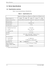
... (Track-Track) • Average • Maximum (Full) 80 GB 60 GB 40 GB 30 GB 156,301,488 117,210,240 78,140,160 58,605,120 512 4,200 rpm ± 1% 7.14 ms 1.5 ms (typ.) Read: 12ms (typ.) 22 ms (typ.) 20 GB 39,070,080 Start time Interface Data Transfer Rate • To/From Media •... under the LBA mode. 8MB 8MB/2MB 2MB 9.5 mm × 100.0 mm × 70.0 mm 99 g (max) 1-4 C141-E192-02EN Table 1.1 Specifications (1/2) MHT2080AT MHT2060AT MHT2040AT MHT2030AT MHT2020AT Format Capacity (*1) Number of the disk...
... (Track-Track) • Average • Maximum (Full) 80 GB 60 GB 40 GB 30 GB 156,301,488 117,210,240 78,140,160 58,605,120 512 4,200 rpm ± 1% 7.14 ms 1.5 ms (typ.) Read: 12ms (typ.) 22 ms (typ.) 20 GB 39,070,080 Start time Interface Data Transfer Rate • To/From Media •... under the LBA mode. 8MB 8MB/2MB 2MB 9.5 mm × 100.0 mm × 70.0 mm 99 g (max) 1-4 C141-E192-02EN Table 1.1 Specifications (1/2) MHT2080AT MHT2060AT MHT2040AT MHT2030AT MHT2020AT Format Capacity (*1) Number of the disk...
Manual/User Guide
Page 30
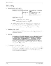
... initialization (formatting) or processing of the DE surface temperature. Also the operating conditions except the environment temperature are correct, the disk drive requires no overhaul for five years or 20,000 hours of operation, whichever occurs first. Device Overview 1.7 Reliability (1) Mean time...damage caused by handling, inappropriate operating environments, defects in the power supply host system, or interface cable. (2) Mean time to repair (MTTR) The mean time to repair (MTTR) is 30 minutes or less, if repaired by external factors, such as follows: Total operation time in ...
... initialization (formatting) or processing of the DE surface temperature. Also the operating conditions except the environment temperature are correct, the disk drive requires no overhaul for five years or 20,000 hours of operation, whichever occurs first. Device Overview 1.7 Reliability (1) Mean time...damage caused by handling, inappropriate operating environments, defects in the power supply host system, or interface cable. (2) Mean time to repair (MTTR) The mean time to repair (MTTR) is 30 minutes or less, if repaired by external factors, such as follows: Total operation time in ...
Manual/User Guide
Page 37
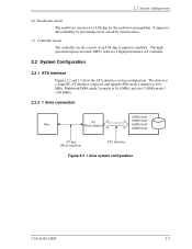
... uses a LSI chip for the read/write preamplifier. The drive has a 44pin PC AT interface connector and supports PIO mode 4 transfer at 16.6 MB/s, Multiword DMA mode 2 transfer at 16.6 MB/s and also U-DMA mode 5 (100 MB/s). 2.2.2 1 drive connection MHT2080AT MMHHTC22006302AATT MMHHTC22004400AATT MHT2030AT Figure 2.2 1 drive system configuration C141-E192-02EN 2-3 It improves data reliability by...
... uses a LSI chip for the read/write preamplifier. The drive has a 44pin PC AT interface connector and supports PIO mode 4 transfer at 16.6 MB/s, Multiword DMA mode 2 transfer at 16.6 MB/s and also U-DMA mode 5 (100 MB/s). 2.2.2 1 drive connection MHT2080AT MMHHTC22006302AATT MMHHTC22004400AATT MHT2030AT Figure 2.2 1 drive system configuration C141-E192-02EN 2-3 It improves data reliability by...
Manual/User Guide
Page 38
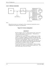
... lines (AT bus) between the HA and the disk drive should be as short as possible. No need to the ATA-6 interface. Thus, it the cause of address decoder, driver, and receiver. The disk drive is not guaranteed. ATA is necessary that the capacitance of... "AT attachment". Device Configuration 2.2.3 2 drives connection (Host adaptor) MHT2080AT MHT2060AT MMHHCT22004302AATT MMHHCT22003400AATT ...
... lines (AT bus) between the HA and the disk drive should be as short as possible. No need to the ATA-6 interface. Thus, it the cause of address decoder, driver, and receiver. The disk drive is not guaranteed. ATA is necessary that the capacitance of... "AT attachment". Device Configuration 2.2.3 2 drives connection (Host adaptor) MHT2080AT MHT2060AT MMHHCT22004302AATT MMHHCT22003400AATT ...
Manual/User Guide
Page 48
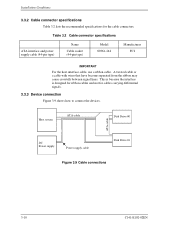
... Disk Drive #1 Figure 3.9 Cable connections 3-10 C141-E192-02EN Installation Conditions 3.3.2 Cable connector specifications Table 3.2 lists the recommended specifications for cables carrying differential signals. 3.3.3 Device connection Figure 3.9 shows how to connect the devices. This is because the interface is ...designed for ribbon cables and not for the cable connectors. Table 3.2 Cable connector specifications ATA interface and power supply cable (44-pin type) Name Cable socket (44-pin...
... Disk Drive #1 Figure 3.9 Cable connections 3-10 C141-E192-02EN Installation Conditions 3.3.2 Cable connector specifications Table 3.2 lists the recommended specifications for cables carrying differential signals. 3.3.3 Device connection Figure 3.9 shows how to connect the devices. This is because the interface is ...designed for ribbon cables and not for the cable connectors. Table 3.2 Cable connector specifications ATA interface and power supply cable (44-pin type) Name Cable socket (44-pin...
Manual/User Guide
Page 51
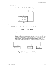
...) setting. 3.4 Jumper Settings Open 1 CA 2 DB Short Note: The CSEL setting is identified as a master drive. The drive is set to the CSEL Line (conducer) of cable selection using unique interface cables. drive drive Figure 3.15 Example (1) of the slave drive does not have a conductor. Figure 3.14 CSEL setting Figure 3.15 and 3.16 show examples of...
...) setting. 3.4 Jumper Settings Open 1 CA 2 DB Short Note: The CSEL setting is identified as a master drive. The drive is set to the CSEL Line (conducer) of cable selection using unique interface cables. drive drive Figure 3.15 Example (1) of the slave drive does not have a conductor. Figure 3.14 CSEL setting Figure 3.15 and 3.16 show examples of...

Manual/User Guide
Page 56
Theory of Device Operation (4) Controller circuit Major functions are listed below. • ATA interface control and data transfer control • Data buffer management • Sector format control • Defect management • ECC control • Error recovery and self-diagnosis Figure 4.1 Power Supply Configuration 4-4 C141-E192-02EN
Theory of Device Operation (4) Controller circuit Major functions are listed below. • ATA interface control and data transfer control • Data buffer management • Sector format control • Defect management • ECC control • Error recovery and self-diagnosis Figure 4.1 Power Supply Configuration 4-4 C141-E192-02EN

Manual/User Guide
Page 75
CHAPTER 5 Interface 5.1 Physical Interface 5.2 Logical Interface 5.3 Host Commands 5.4 Command Protocol 5.5 Ultra DMA Feature Set 5.6 Timing This chapter gives details about the interface, and the interface commands and timings. C141-E192-02EN 5-1
CHAPTER 5 Interface 5.1 Physical Interface 5.2 Logical Interface 5.3 Host Commands 5.4 Command Protocol 5.5 Ultra DMA Feature Set 5.6 Timing This chapter gives details about the interface, and the interface commands and timings. C141-E192-02EN 5-1

Manual/User Guide
Page 76
... DA 0-2: DEVICE ADDRESS CS0-: CHIP SELECT 0 CS1-: CHIP SELECT 1 RESET-: RESET CSEL: CABLE SELECT MSTR: Master ENCSEL: ENABLE CSEL +5V DC: +5 volt GND: GROUND Figure 5.1 Interface signals 5-2 C141-E192-02EN Interface 5.1 Physical Interface 5.1.1 Interface signals Figure 5.1 shows the...
... DA 0-2: DEVICE ADDRESS CS0-: CHIP SELECT 0 CS1-: CHIP SELECT 1 RESET-: RESET CSEL: CABLE SELECT MSTR: Master ENCSEL: ENABLE CSEL +5V DC: +5 volt GND: GROUND Figure 5.1 Interface signals 5-2 C141-E192-02EN Interface 5.1 Physical Interface 5.1.1 Interface signals Figure 5.1 shows the...

Manual/User Guide
Page 77
... DATA2 DATA1 DATA0 GND DMARQ DIOW-, STOP DIOR-, HDMRDY, HSTROBE IORDY, DDMARDY, DSTROBE DMACK- INTRQ DA1 DA0 CS0- 5.1 Physical Interface 5.1.2 Signal assignment on the connector Table 5.1 shows the signal assignment on the interface connector Pin No. A C E 1 3 5 7 9 11 13 15 17 19 21 23 25 27 29 31 33 35...) 2 GND 4 DATA8 6 DATA9 8 DATA10 10 DATA11 12 DATA12 14 DATA13 16 DATA14 18 DATA15 20 (KEY) 22 GND 24 GND 26 GND 28 CSEL 30 GND 32 reserved (IOCS16-) 34 PDIAG-, CBLID- 36 DA2 38 CS1- 40 GND 42 +5 VDC 44 unused C141-E192-02EN 5-3 Table 5.1 Signal assignment on ...
... DATA2 DATA1 DATA0 GND DMARQ DIOW-, STOP DIOR-, HDMRDY, HSTROBE IORDY, DDMARDY, DSTROBE DMACK- INTRQ DA1 DA0 CS0- 5.1 Physical Interface 5.1.2 Signal assignment on the connector Table 5.1 shows the signal assignment on the interface connector Pin No. A C E 1 3 5 7 9 11 13 15 17 19 21 23 25 27 29 31 33 35...) 2 GND 4 DATA8 6 DATA9 8 DATA10 10 DATA11 12 DATA12 14 DATA13 16 DATA14 18 DATA15 20 (KEY) 22 GND 24 GND 26 GND 28 CSEL 30 GND 32 reserved (IOCS16-) 34 PDIAG-, CBLID- 36 DA2 38 CS1- 40 GND 42 +5 VDC 44 unused C141-E192-02EN 5-3 Table 5.1 Signal assignment on ...

Manual/User Guide
Page 78
Interface [signal] ENCSEL MSTRPUSRESETDATA 0-15 DIOWSTOP DIORHDMARDY- HSTROBE INTRQ [I/O] I I I I I/O I I I I I , Master/slave setting Pin A, B, C, D open: Master setting Pin A, B Short: Slave setting When pin C is disabled. Reset signal ... signal is asserted for Ultra DMA data In transfer (READ DMA command). Pins B and D Open: Sets master/slave using the CSEL signal is grounded, the drive does not spin up at power on . MSTR, I O [Description] This signal is used for data transfer Signal asserted by the host before data is ready...
Interface [signal] ENCSEL MSTRPUSRESETDATA 0-15 DIOWSTOP DIORHDMARDY- HSTROBE INTRQ [I/O] I I I I I/O I I I I I , Master/slave setting Pin A, B, C, D open: Master setting Pin A, B Short: Slave setting When pin C is disabled. Reset signal ... signal is asserted for Ultra DMA data In transfer (READ DMA command). Pins B and D Open: Sets master/slave using the CSEL signal is grounded, the drive does not spin up at power on . MSTR, I O [Description] This signal is used for data transfer Signal asserted by the host before data is ready...

Manual/User Guide
Page 79
... a response that the host system receive data or to detect the type of the DSTROBE signal latch data from Data 15-0 into the host. 5.1 Physical Interface [signal] CS0- CS1- DA 0-2 KEY PDIAG- [I/O] I I I I /O DASP- I /O CBLID- This signal is used to indicate that the device is active and a slave device is pulled up...
... a response that the host system receive data or to detect the type of the DSTROBE signal latch data from Data 15-0 into the host. 5.1 Physical Interface [signal] CS0- CS1- DA 0-2 KEY PDIAG- [I/O] I I I I /O DASP- I /O CBLID- This signal is used to indicate that the device is active and a slave device is pulled up...
Manual/User Guide
Page 80
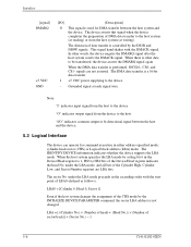
... the host system changes the assignment of data transfer is not changed. In other data to be transferred, the device asserts the DMARQ signal again. Interface [signal] DMARQ +5 VDC GND [I/O] O I - [Description] This signal is a 16-bit data transfer. +5 VDC power supplying to the device. The DMA ...data transfer is used for DMA transfer between the host and the device. 5.2 Logical Interface The device can operate for command execution in the Device/Head register to 1, HS3 to the host. This signal hand shakes with the start...
... the host system changes the assignment of data transfer is not changed. In other data to be transferred, the device asserts the DMARQ signal again. Interface [signal] DMARQ +5 VDC GND [I/O] O I - [Description] This signal is a 16-bit data transfer. +5 VDC power supplying to the device. The DMA ...data transfer is used for DMA transfer between the host and the device. 5.2 Logical Interface The device can operate for command execution in the Device/Head register to 1, HS3 to the host. This signal hand shakes with the start...
