Manual/User Guide
Page 5
... in this manual. Glossary The glossary describes the technical terms that the reader has a basic knowledge of hard disk drives and their features. Preface This manual describes MHT2080AT/ MHT2060AT/ MHT2040AT/ MHT2030AT/ MHT2020AT models of the disk drive and describes their implementations in computer systems. This manual consists of seven chapters and sections explaining the...
... in this manual. Glossary The glossary describes the technical terms that the reader has a basic knowledge of hard disk drives and their features. Preface This manual describes MHT2080AT/ MHT2060AT/ MHT2040AT/ MHT2030AT/ MHT2020AT models of the disk drive and describes their implementations in computer systems. This manual consists of seven chapters and sections explaining the...
Manual/User Guide
Page 6
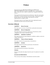
...message begins and ends. Hexadecimal numbers are represented as shown in the following examples: 010 or 010b. This alert signal also indicates that the disk drive is centered, followed below by external magnetic fields. ii C141-E192-02EN In the text, the alert signal is not affected by the indented ... conventions to be used in offices or computer rooms. Conventions An MHT series device is an example: (Example) Data corruption: Avoid mounting the disk drive near strong magnetic sources such as a "hard disk drive," "HDD," "drive," or "device" in the "Important Alert Items."
...message begins and ends. Hexadecimal numbers are represented as shown in the following examples: 010 or 010b. This alert signal also indicates that the disk drive is centered, followed below by external magnetic fields. ii C141-E192-02EN In the text, the alert signal is not affected by the indented ... conventions to be used in offices or computer rooms. Conventions An MHT series device is an example: (Example) Data corruption: Avoid mounting the disk drive near strong magnetic sources such as a "hard disk drive," "HDD," "drive," or "device" in the "Important Alert Items."

Manual/User Guide
Page 7
... this manual and forward it to defects that involve adjustment, repair, or replacement. Fujitsu is not liable for users to understand, opinions from readers are needed. Preface Attention Please forward any other disk drive defects, such as those caused by user misoperation or mishandling, inappropriate operating environments, ... write your opinions or requests on the Comment at the back of this manual. C141-E192-02EN iii Liability Exception "Disk drive defects" refers to the address described in the power supply or cable, problems of the host system, or other causes outside the disk...
... this manual and forward it to defects that involve adjustment, repair, or replacement. Fujitsu is not liable for users to understand, opinions from readers are needed. Preface Attention Please forward any other disk drive defects, such as those caused by user misoperation or mishandling, inappropriate operating environments, ... write your opinions or requests on the Comment at the back of this manual. C141-E192-02EN iii Liability Exception "Disk drive defects" refers to the address described in the power supply or cable, problems of the host system, or other causes outside the disk...
Manual/User Guide
Page 9
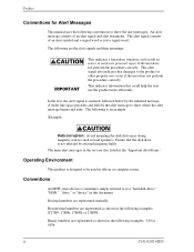
... not affected by the edges. Damage: Do not press the cover of the disk drive. Pressing it by external magnetic fields. Important Alert Items Important Alert Messages The important alert messages in this manual are as loud speakers. Static: When ... personal injury if the user does not perform the procedure correctly. C141-E192-02EN v Do not touch the printed circuit board, but hold it too hard, the cover and the spindle motor contact, which may cause damage to the product or other property, may occur if the user does not perform...
... not affected by the edges. Damage: Do not press the cover of the disk drive. Pressing it by external magnetic fields. Important Alert Items Important Alert Messages The important alert messages in this manual are as loud speakers. Static: When ... personal injury if the user does not perform the procedure correctly. C141-E192-02EN v Do not touch the printed circuit board, but hold it too hard, the cover and the spindle motor contact, which may cause damage to the product or other property, may occur if the user does not perform...
Manual/User Guide
Page 11
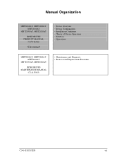
Manual Organization MHT2080AT, MHT2060AT, MHT2040AT MHT2030AT, MHT2020AT DISK DRIVES PRODUCT MANUAL (C141-E192) • Device Overview • Device Configuration • Installation Conditions • Theory of Device Operation • Interface • Operations MHT2080AT, MHT2060AT, MHT2040AT MHT2030AT, MHT2020AT DISK DRIVES MAINTENANCE MANUAL (C141-F063) • Maintenance and Diagnosis • Removal and Replacement Procedure C141-E192-02EN vii
Manual Organization MHT2080AT, MHT2060AT, MHT2040AT MHT2030AT, MHT2020AT DISK DRIVES PRODUCT MANUAL (C141-E192) • Device Overview • Device Configuration • Installation Conditions • Theory of Device Operation • Interface • Operations MHT2080AT, MHT2060AT, MHT2040AT MHT2030AT, MHT2020AT DISK DRIVES MAINTENANCE MANUAL (C141-F063) • Maintenance and Diagnosis • Removal and Replacement Procedure C141-E192-02EN vii
Manual/User Guide
Page 14
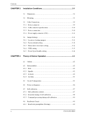
... 3-9 3.3.2 Cable connector specifications 3-10 3.3.3 Device connection 3-10 3.3.4 Power supply connector (CN1 3-11 3.4 Jumper Settings 3-11 3.4.1 Location of setting jumpers 3-11 3.4.2 Factory default setting 3-12 3.4.3 Master drive-slave drive setting 3-12 3.4.4 CSEL setting 3-13 3.4.5 Power Up in Standby setting 3-14 CHAPTER 4 Theory of Device Operation 4-1 4.1 Outline ...4-2 4.2 Subassemblies 4-2 4.2.1 Disk...4-2 4.2.2 Spindle 4-2 4.2.3 Actuator 4-2 4.2.4 Air filter 4-3 4.3 Circuit...
... 3-9 3.3.2 Cable connector specifications 3-10 3.3.3 Device connection 3-10 3.3.4 Power supply connector (CN1 3-11 3.4 Jumper Settings 3-11 3.4.1 Location of setting jumpers 3-11 3.4.2 Factory default setting 3-12 3.4.3 Master drive-slave drive setting 3-12 3.4.4 CSEL setting 3-13 3.4.5 Power Up in Standby setting 3-14 CHAPTER 4 Theory of Device Operation 4-1 4.1 Outline ...4-2 4.2 Subassemblies 4-2 4.2.1 Disk...4-2 4.2.2 Spindle 4-2 4.2.3 Actuator 4-2 4.2.4 Air filter 4-3 4.3 Circuit...
Manual/User Guide
Page 18
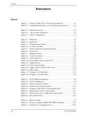
...when power is turned off 1-6 Figure 1.2 Current fluctuation (Typ.) at +5 V when power is turned on 1-8 Figure 2.1 Disk drive outerview 2-2 Figure 2.2 1 drive system configuration 2-3 Figure 2.3 2 drives configuration 2-4 Figure 3.1 Dimensions 3-2 Figure 3.2 Orientation 3-3 Figure 3.3 Mounting frame structure 3-4 Figure 3.4 Location of breather 3-5 Figure 3.5... 3.11 Jumper location 3-11 Figure 3.12 Factory default setting 3-12 Figure 3.13 Jumper setting of master or slave drive 3-12 Figure 3.14 CSEL setting 3-13 Figure 3.15 Example (1) of Cable Select 3-13 Figure 3.16 Example (2)...
...when power is turned off 1-6 Figure 1.2 Current fluctuation (Typ.) at +5 V when power is turned on 1-8 Figure 2.1 Disk drive outerview 2-2 Figure 2.2 1 drive system configuration 2-3 Figure 2.3 2 drives configuration 2-4 Figure 3.1 Dimensions 3-2 Figure 3.2 Orientation 3-3 Figure 3.3 Mounting frame structure 3-4 Figure 3.4 Location of breather 3-5 Figure 3.5... 3.11 Jumper location 3-11 Figure 3.12 Factory default setting 3-12 Figure 3.13 Jumper setting of master or slave drive 3-12 Figure 3.14 CSEL setting 3-13 Figure 3.15 Example (1) of Cable Select 3-13 Figure 3.16 Example (2)...
Manual/User Guide
Page 21
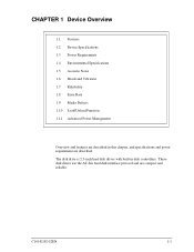
The disk drive is 2.5-inch hard disk drives with built-in this chapter, and specifications and power requirement are described. C141-E192-02EN 1-1 These disk drives use the AT-bus hard disk interface protocol and are compact and reliable. CHAPTER 1 Device Overview 1.1 Features 1.2 Device Specifications 1.3 Power Requirements 1.4 Environmental Specifications 1.5 Acoustic Noise 1.6 Shock and Vibration 1.7 Reliability 1.8 Error Rate 1.9 Media Defects 1.10 Load/Unload Function 1.11 Advanced Power Management Overview and features are described in disk controllers.
The disk drive is 2.5-inch hard disk drives with built-in this chapter, and specifications and power requirement are described. C141-E192-02EN 1-1 These disk drives use the AT-bus hard disk interface protocol and are compact and reliable. CHAPTER 1 Device Overview 1.1 Features 1.2 Device Specifications 1.3 Power Requirements 1.4 Environmental Specifications 1.5 Acoustic Noise 1.6 Shock and Vibration 1.7 Reliability 1.8 Error Rate 1.9 Media Defects 1.10 Load/Unload Function 1.11 Advanced Power Management Overview and features are described in disk controllers.

Manual/User Guide
Page 22
... to 8820 m/s2 (900G). 1-2 C141-E192-02EN The disk drive has a formatted capacity of 80 GB (MHT2080AT), 60 GB (MHT2060AT), 40 GB (MHT2040AT), 30 GB (MHT2030AT) and 20 GB (MHT2020AT) respectively. (3) High-speed Transfer rate The disk drive (the MHT Series) has an internal data rate up to 40 GB (formatted) on one disk using the RLL recording method and...
... to 8820 m/s2 (900G). 1-2 C141-E192-02EN The disk drive has a formatted capacity of 80 GB (MHT2080AT), 60 GB (MHT2060AT), 40 GB (MHT2040AT), 30 GB (MHT2030AT) and 20 GB (MHT2020AT) respectively. (3) High-speed Transfer rate The disk drive (the MHT Series) has an internal data rate up to 40 GB (formatted) on one disk using the RLL recording method and...

Manual/User Guide
Page 23
...to the disk media. Executing a diagnostic function of the smart command invokes selfdiagnosis. (7) Write cache When the disk drive receives a write command, the disk drive posts the command completion at writing. This feature reduces the access time at completion of transferring data to the data...media. The next disk read command would normally cause another disk access. 1.1 Features 1.1.3 Interface (1) Connection to ATA interface The disk drive has built-in controllers compatible with the read-ahead cache system described in item (3) and the write cache described in the buffer ...
...to the disk media. Executing a diagnostic function of the smart command invokes selfdiagnosis. (7) Write cache When the disk drive receives a write command, the disk drive posts the command completion at writing. This feature reduces the access time at completion of transferring data to the data...media. The next disk read command would normally cause another disk access. 1.1 Features 1.1.3 Interface (1) Connection to ATA interface The disk drive has built-in controllers compatible with the read-ahead cache system described in item (3) and the write cache described in the buffer ...
Manual/User Guide
Page 24
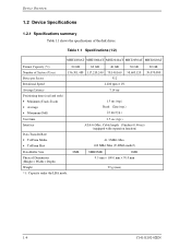
... Latency Positioning time (read and seek) • Minimum (Track-Track) • Average • Maximum (Full) 80 GB 60 GB 40 GB 30 GB 156,301,488 117,210,240 78,140,160 58,605,120 512 4,200 rpm ± 1% 7.14 ms 1.5 ...ms (typ.) Read: 12ms (typ.) 22 ms (typ.) 20 GB 39,070,080 Start time Interface Data Transfer Rate &#... 70.0 mm 99 g (max) 1-4 C141-E192-02EN Table 1.1 Specifications (1/2) MHT2080AT MHT2060AT MHT2040AT MHT2030AT MHT2020AT Format Capacity (*1) Number of the disk...
... Latency Positioning time (read and seek) • Minimum (Track-Track) • Average • Maximum (Full) 80 GB 60 GB 40 GB 30 GB 156,301,488 117,210,240 78,140,160 58,605,120 512 4,200 rpm ± 1% 7.14 ms 1.5 ...ms (typ.) Read: 12ms (typ.) 22 ms (typ.) 20 GB 39,070,080 Start time Interface Data Transfer Rate &#... 70.0 mm 99 g (max) 1-4 C141-E192-02EN Table 1.1 Specifications (1/2) MHT2080AT MHT2060AT MHT2040AT MHT2030AT MHT2020AT Format Capacity (*1) Number of the disk...
Manual/User Guide
Page 25
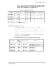
...drive. of Sectors 63 63 63 63 63 1.2.2 Model and product number Table 1.2 lists the model names and product numbers of Heads 16 16 16 16 16 No. Table 1.2 Examples of model names and product numbers Model Name MHT2080AT MHT2060AT MHT2040AT MHT2030AT MHT2020AT Capacity (user area) 80 GB 60 GB 40 GB 30 GB 20 GB...are different from those for the units of BIOS parameter. of Cylinder MHT2080AT 8.45 GB 16,383 MHT2060AT 8.45 GB 16,383 MHT2040AT 8.45 GB 16,383 MHT2030AT 8.45 GB 16,383 MHT2020AT 8.45 GB 16,383 *1 On using the BIOS setup utility on the host. 1.2 Device ...
...drive. of Sectors 63 63 63 63 63 1.2.2 Model and product number Table 1.2 lists the model names and product numbers of Heads 16 16 16 16 16 No. Table 1.2 Examples of model names and product numbers Model Name MHT2080AT MHT2060AT MHT2040AT MHT2030AT MHT2020AT Capacity (user area) 80 GB 60 GB 40 GB 30 GB 20 GB...are different from those for the units of BIOS parameter. of Cylinder MHT2080AT 8.45 GB 16,383 MHT2060AT 8.45 GB 16,383 MHT2040AT 8.45 GB 16,383 MHT2030AT 8.45 GB 16,383 MHT2020AT 8.45 GB 16,383 *1 On using the BIOS setup utility on the host. 1.2 Device ...
Manual/User Guide
Page 29
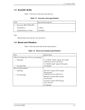
... 0-peak (900G 0-peak) 1ms duration 1176 m/s2 0-peak (120G 0-peak) 11ms duration (no damage) C141-E192-02EN 1-9 Table 1.5 Acoustic noise specification Item • Idle mode (DRIVE READY) Sound Power Sound Pressure (at 0.3m) Specification (typical) 2.3B(A) 24.0dB(A) Note: Measure the noise from the cover top surface. 1.6 Shock and Vibration Table...
... 0-peak (900G 0-peak) 1ms duration 1176 m/s2 0-peak (120G 0-peak) 11ms duration (no damage) C141-E192-02EN 1-9 Table 1.5 Acoustic noise specification Item • Idle mode (DRIVE READY) Sound Power Sound Pressure (at 0.3m) Specification (typical) 2.3B(A) 24.0dB(A) Note: Measure the noise from the cover top surface. 1.6 Shock and Vibration Table...
Manual/User Guide
Page 30
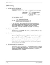
...operating environments, defects in the power supply host system, or interface cable. (2) Mean time to repair (MTTR) The mean time to repair (MTTR) is 30 minutes or less, if repaired by external factors, such as follows: Total operation time in all fields MTBF= (H) number of device failure in all fields..." refers to item (3) in Subsection 3.2 for five years or 20,000 hours of operation, whichever occurs first. Disk drive defects do not include failures caused by a specialist maintenance staff member. (3) Service life In situations where management and handling are based on the MTBF ...
...operating environments, defects in the power supply host system, or interface cable. (2) Mean time to repair (MTTR) The mean time to repair (MTTR) is 30 minutes or less, if repaired by external factors, such as follows: Total operation time in all fields MTBF= (H) number of device failure in all fields..." refers to item (3) in Subsection 3.2 for five years or 20,000 hours of operation, whichever occurs first. Disk drive defects do not include failures caused by a specialist maintenance staff member. (3) Service life In situations where management and handling are based on the MTBF ...
Manual/User Guide
Page 31
... which alternative blocks can be recovered by one retry shall occur no more than 10 times in the error rate count below are executed. • Hard Reset • STANDBY • STANDBY IMMEDIATE • SLEEP • IDLE Emergency Unload other than 10 times when reading data of 1014 bits.... disk and unloads the head from the factory (low level format). Read retries are executed according to the disk drive's error recovery procedure, and include read retries of drive without user's retry and ECC corrections shall occur no more than Normal Unload is performed when the power is shut...
... which alternative blocks can be recovered by one retry shall occur no more than 10 times in the error rate count below are executed. • Hard Reset • STANDBY • STANDBY IMMEDIATE • SLEEP • IDLE Emergency Unload other than 10 times when reading data of 1014 bits.... disk and unloads the head from the factory (low level format). Read retries are executed according to the disk drive's error recovery procedure, and include read retries of drive without user's retry and ECC corrections shall occur no more than Normal Unload is performed when the power is shut...
Manual/User Guide
Page 32
The disk drive complies with a Sector Count register of the SET FEATURES(EF) command. BFh : Mode-1 Active Idle → Low Power Idle (Default) SC = 01h - 7Fh : Mode-2 Active ... whether bit 7 of the status register was set to '0'. (wait to complete STANDBY IMMEDIATE command) 4) HDD power supply cutting 1.11 Advanced Power Management The disk drive shifts to the three kinds of APM modes automatically under the Idle condition. The APM mode can be executed. FEh : Mode-0 Active Idle → Low...
The disk drive complies with a Sector Count register of the SET FEATURES(EF) command. BFh : Mode-1 Active Idle → Low Power Idle (Default) SC = 01h - 7Fh : Mode-2 Active ... whether bit 7 of the status register was set to '0'. (wait to complete STANDBY IMMEDIATE command) 4) HDD power supply cutting 1.11 Advanced Power Management The disk drive shifts to the three kinds of APM modes automatically under the Idle condition. The APM mode can be executed. FEh : Mode-0 Active Idle → Low...
Manual/User Guide
Page 35
C141-E192-02EN 2-1 CHAPTER 2 Device Configuration 2.1 Device Configuration 2.2 System Configuration This chapter describes the internal configurations of the hard disk drives and the configuration of the systems in which they operate.
C141-E192-02EN 2-1 CHAPTER 2 Device Configuration 2.1 Device Configuration 2.2 System Configuration This chapter describes the internal configurations of the hard disk drives and the configuration of the systems in which they operate.
Manual/User Guide
Page 36
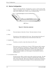
...The disk enclosure features a closed loop air circulation system that relies on the blower effect of while the disk is fixed by a direct drive Sensor-less DC motor. (4) Actuator The actuator uses a revolving voice coil motor (VCM) structure which consumes low power and generates very ...little heat. MHT Series Figure 2.1 Disk drive outerview (1) Disk The outer diameter of the load/unload (L/UL) type. The inner diameter is 20 mm. (2) Head The heads are rotated by...
...The disk enclosure features a closed loop air circulation system that relies on the blower effect of while the disk is fixed by a direct drive Sensor-less DC motor. (4) Actuator The actuator uses a revolving voice coil motor (VCM) structure which consumes low power and generates very ...little heat. MHT Series Figure 2.1 Disk drive outerview (1) Disk The outer diameter of the load/unload (L/UL) type. The inner diameter is 20 mm. (2) Head The heads are rotated by...
Manual/User Guide
Page 37
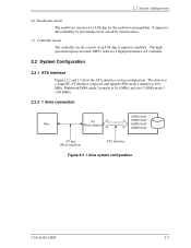
... connector and supports PIO mode 4 transfer at 16.6 MB/s, Multiword DMA mode 2 transfer at 16.6 MB/s and also U-DMA mode 5 (100 MB/s). 2.2.2 1 drive connection MHT2080AT MMHHTC22006302AATT MMHHTC22004400AATT MHT2030AT Figure 2.2 1 drive system configuration C141-E192-02EN 2-3 It improves data reliability by preventing errors caused by external noise. (7) Controller circuit The controller circuit consists of...
... connector and supports PIO mode 4 transfer at 16.6 MB/s, Multiword DMA mode 2 transfer at 16.6 MB/s and also U-DMA mode 5 (100 MB/s). 2.2.2 1 drive connection MHT2080AT MMHHTC22006302AATT MMHHTC22004400AATT MHT2030AT Figure 2.2 1 drive system configuration C141-E192-02EN 2-3 It improves data reliability by preventing errors caused by external noise. (7) Controller circuit The controller circuit consists of...
Manual/User Guide
Page 38
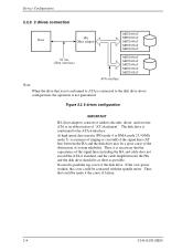
... transfer (PIO mode 4 or DMA mode 2 U-DMA mode 5), occurrence of ringing or crosstalk of the signal lines (AT bus) between the HA and the disk drive should be as short as possible. If the over-power worked, the cover could be made it is necessary that is not conformed to ATA... including the HA and cable does not exceed the ATA-6 standard, and the cable length between the HA and the disk drive may be a great cause of the obstruction of system reliability. The disk drive is an abbreviation of "AT attachment". Thus, it the cause of address decoder, driver, and receiver. Figure...
... transfer (PIO mode 4 or DMA mode 2 U-DMA mode 5), occurrence of ringing or crosstalk of the signal lines (AT bus) between the HA and the disk drive should be as short as possible. If the over-power worked, the cover could be made it is necessary that is not conformed to ATA... including the HA and cable does not exceed the ATA-6 standard, and the cable length between the HA and the disk drive may be a great cause of the obstruction of system reliability. The disk drive is an abbreviation of "AT attachment". Thus, it the cause of address decoder, driver, and receiver. Figure...


