
Manual/User Guide
Page 2
... life or cause a physical injury (hereafter referred to the application or use . Read thoroughly before using this manual, its updates or supplements, whether such errors or omissions result from suffering damage to consult our sales representative before embarking on such specialized use ... use ). IMPORTANT NOTE TO USERS READ THE ENTIRE MANUAL CAREFULLY BEFORE USING THIS PRODUCT. All Rights Reserved, Copyright FUJITSU LIMITED 2003 Use this product only after thoroughly reading and understanding especially the section "Important Alert Items" in standard applications such ...
... life or cause a physical injury (hereafter referred to the application or use . Read thoroughly before using this manual, its updates or supplements, whether such errors or omissions result from suffering damage to consult our sales representative before embarking on such specialized use ... use ). IMPORTANT NOTE TO USERS READ THE ENTIRE MANUAL CAREFULLY BEFORE USING THIS PRODUCT. All Rights Reserved, Copyright FUJITSU LIMITED 2003 Use this product only after thoroughly reading and understanding especially the section "Important Alert Items" in standard applications such ...

Manual/User Guide
Page 58
...reached rated speed, the head assembly is turned on, the disk drive executes the MPU bus test, internal register read/write test, and work RAM read /write test) after enabling response to the actuator, and updates the calibrating value. Theory of Device Operation 4.4 Power-on Sequence... Figure 4.3 describes the operation sequence of self -calibration. This collects data for execution of the disk drive at power-on the disk. When the self-diagnosis...
...reached rated speed, the head assembly is turned on, the disk drive executes the MPU bus test, internal register read/write test, and work RAM read /write test) after enabling response to the actuator, and updates the calibrating value. Theory of Device Operation 4.4 Power-on Sequence... Figure 4.3 describes the operation sequence of self -calibration. This collects data for execution of the disk drive at power-on the disk. When the self-diagnosis...

Manual/User Guide
Page 60
...forces are compensated by execution of any cylinder. To compensate torque varying by the compensation value. In the self-calibration, the compensating value is updated using the value in the SA area. To compensate torque constant value change is stored in the SA area. 4.5.2 Execution timing of self...-calibration Self-calibration is performed once when power is measured at the measuring cylinder on the cylinder that the head is measured for each drive, and varies depending on each time one of the following events occur: • When it detects an error. For sensing, the ...
...forces are compensated by execution of any cylinder. To compensate torque varying by the compensation value. In the self-calibration, the compensating value is updated using the value in the SA area. To compensate torque constant value change is stored in the SA area. 4.5.2 Execution timing of self...-calibration Self-calibration is performed once when power is measured at the measuring cylinder on the cylinder that the head is measured for each drive, and varies depending on each time one of the following events occur: • When it detects an error. For sensing, the ...

Manual/User Guide
Page 71
... is detected the head is moved slowly toward the inner circumference at the reference cylinder from the outside of sampling time, executes calculation, and updates the VCM drive current. d) If the head is stopped at a constant speed. The MPU fetches the position sense data on the servo frame at ontrack so that...
... is detected the head is moved slowly toward the inner circumference at the reference cylinder from the outside of sampling time, executes calculation, and updates the VCM drive current. d) If the head is stopped at a constant speed. The MPU fetches the position sense data on the servo frame at ontrack so that...

Manual/User Guide
Page 84
.... Under the LBA mode of the EXT system command, LBA bits 31 to 24 are set in the first setting, and LBA bits 7 to 0 are updated to the current cylinder number. At the end of a command, the contents of this register are set in the second setting. (6) Cylinder Low register (X'1F4... the LBA mode of the EXT system command, LBA bits 39 to 32 are set in the first setting, and LBA bits 15 to 8 are updated to the current cylinder number. At the end of a command, the contents of this register are set in the second setting. (7) Cylinder High register (X'1F5...
.... Under the LBA mode of the EXT system command, LBA bits 31 to 24 are set in the first setting, and LBA bits 7 to 0 are updated to the current cylinder number. At the end of a command, the contents of this register are set in the second setting. (6) Cylinder Low register (X'1F4... the LBA mode of the EXT system command, LBA bits 39 to 32 are set in the first setting, and LBA bits 15 to 8 are updated to the current cylinder number. At the end of a command, the contents of this register are set in the second setting. (7) Cylinder High register (X'1F5...

Manual/User Guide
Page 85
... Acknowledge (the host system acknowledges the interrupt). Bit 0: HS1 CHS mode head address 1 (21). When the BSY bit is 1, other bits in this register are updated at the completion of each command. 5.2 Logical Interface (8) Device/Head register (X'1F6') The contents of this register is read. bit 26 for the slave device...
... Acknowledge (the host system acknowledges the interrupt). Bit 0: HS1 CHS mode head address 1 (21). When the BSY bit is 1, other bits in this register are updated at the completion of each command. 5.2 Logical Interface (8) Device/Head register (X'1F6') The contents of this register is read. bit 26 for the slave device...

Manual/User Guide
Page 103
... End sector No. / LBA [LSB] 00 (*1) Error information *1 If the command is set in the LBA mode. When the device completes the calibration, the device updates the Status register, clears the BSY bit, and generates an interrupt.
... End sector No. / LBA [LSB] 00 (*1) Error information *1 If the command is set in the LBA mode. When the device completes the calibration, the device updates the Status register, clears the BSY bit, and generates an interrupt.
Manual/User Guide
Page 141
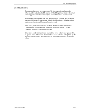
... the SMART Enable Operations (with the command, the Aborted Command error is issued. If the failure prediction function is enabled, the device collects and updates data on the subcommand specified in the CH register). If the failure prediction function is disabled, the device returns the Aborted Command error to subcommands... other than those of items whose data is collected and updated by the device in order to predict device failures are hereinafter referred to as attribute values.
... the SMART Enable Operations (with the command, the Aborted Command error is issued. If the failure prediction function is enabled, the device collects and updates data on the subcommand specified in the CH register). If the failure prediction function is disabled, the device returns the Aborted Command error to subcommands... other than those of items whose data is collected and updated by the device in order to predict device failures are hereinafter referred to as attribute values.

Manual/User Guide
Page 142
... were saved, then the attributes are collected. SMART SAVE ATTRIBUTE VALUES: When the device receives this subcommand asserts the BSY bit and saves all the updated attribute values. SMART EXECUTIVE OFF-LINE IMMEDIATE: A device which receives this subcommand, a device asserts BSY, enables or disables the automatic attribute save function"). In the...
... were saved, then the attributes are collected. SMART SAVE ATTRIBUTE VALUES: When the device receives this subcommand asserts the BSY bit and saves all the updated attribute values. SMART EXECUTIVE OFF-LINE IMMEDIATE: A device which receives this subcommand, a device asserts BSY, enables or disables the automatic attribute save function"). In the...
Manual/User Guide
Page 147
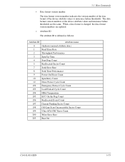
...number The data format version number indicates the version number of the data format of the device attribute values and insurance failure thresholds are updated. • Attribute ID The attribute ID is changed, the data format version numbers are the same. When a data format is defined...Start/Stop Count 5 Reallocated Sector Count 7 Seek Error Rate 8 Seek Time Performance 9 Power-On Hours Count 10 Spin Retry Count 12 Drive Power Cycle Count 192 Emergency Retract Cycle Count 193 Load/Unload Cycle Count 194 HDA Temperature 195 ECC On the Flag Count 196 Reallocated Event...
...number The data format version number indicates the version number of the data format of the device attribute values and insurance failure thresholds are updated. • Attribute ID The attribute ID is changed, the data format version numbers are the same. When a data format is defined...Start/Stop Count 5 Reallocated Sector Count 7 Seek Error Rate 8 Seek Time Performance 9 Power-On Hours Count 10 Spin Retry Count 12 Drive Power Cycle Count 192 Emergency Retract Cycle Count 193 Load/Unload Cycle Count 194 HDA Temperature 195 ECC On the Flag Count 196 Reallocated Event...

Manual/User Guide
Page 148
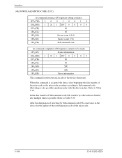
... 1, it indicates the attribute that represents the number of a failure. If the attribute value is larger than the threshold value, the drive is determined to be collected/saved even if the drive fault prediction function is to 01h, the higher the possibility of occurrences. Interface • Status Flag Bit 0 1 2 3 4 5 6 to 15 Meaning.... • Attribute value for the ultra ATA CRC error rate). It indicates that represents an error rate. If this bit 1, it indicates the attribute only updated by an online test (off-line test).
... 1, it indicates the attribute that represents the number of a failure. If the attribute value is larger than the threshold value, the drive is determined to be collected/saved even if the drive fault prediction function is to 01h, the higher the possibility of occurrences. Interface • Status Flag Bit 0 1 2 3 4 5 6 to 15 Meaning.... • Attribute value for the ultra ATA CRC error rate). It indicates that represents an error rate. If this bit 1, it indicates the attribute only updated by an online test (off-line test).
Manual/User Guide
Page 180
Refer to Table 5-19. In the data transfer of Subcommand code:01h, transfer by Subcommand code:07h, reactivates in the device for the update of the rewriting microcode of rewriting by which data is divided into multiple times is possible. After the designation of the microcode. 5-106 C141-E192-...
Refer to Table 5-19. In the data transfer of Subcommand code:01h, transfer by Subcommand code:07h, reactivates in the device for the update of the rewriting microcode of rewriting by which data is divided into multiple times is possible. After the designation of the microcode. 5-106 C141-E192-...
