Manual/User Guide
Page 38
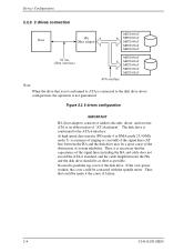
... transfer (PIO mode 4 or DMA mode 2 U-DMA mode 5), occurrence of ringing or crosstalk of the signal lines (AT bus) between the HA and the disk drive should be a great cause of the obstruction of "AT attachment". If the over-power worked, the cover could be contacted with the spindle motor. ATA... is not guaranteed. No need to push the top cover of address decoder, driver, and receiver. Thus, that could be made it is necessary that is not conformed to ATA is connected to the ATA-6 interface. Figure...
... transfer (PIO mode 4 or DMA mode 2 U-DMA mode 5), occurrence of ringing or crosstalk of the signal lines (AT bus) between the HA and the disk drive should be a great cause of the obstruction of "AT attachment". If the over-power worked, the cover could be contacted with the spindle motor. ATA... is not guaranteed. No need to push the top cover of address decoder, driver, and receiver. Thus, that could be made it is necessary that is not conformed to ATA is connected to the ATA-6 interface. Figure...
Manual/User Guide
Page 46
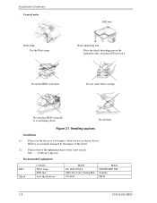
... HDD vertically to avoid falling down. General notes Wrist strap Use the Wrist strap. Recommended equipments ESD Shock Contents Wrist strap ESD mat Low shock driver Model JX-1200-3056-8 SKY-8A (Color Seiden Mat) SS-6500 Maker SUMITOMO 3M Achilles HIOS 3-8 C141-E192-02EN Do not hit HDD each other... shock absorbing mat on the operation table, and place ESD mat on it. Do not drop. HDD is occasionally damaged by the impact of the driver. (2) Please observe the tightening torque of a low impact when you use an electric...
... HDD vertically to avoid falling down. General notes Wrist strap Use the Wrist strap. Recommended equipments ESD Shock Contents Wrist strap ESD mat Low shock driver Model JX-1200-3056-8 SKY-8A (Color Seiden Mat) SS-6500 Maker SUMITOMO 3M Achilles HIOS 3-8 C141-E192-02EN Do not hit HDD each other... shock absorbing mat on the operation table, and place ESD mat on it. Do not drop. HDD is occasionally damaged by the impact of the driver. (2) Please observe the tightening torque of a low impact when you use an electric...
Manual/User Guide
Page 55
... dirt from the head. The MPU precisely sets each head on the track according on the servo information on the data surface. When disk drives are two types of two circuits; The breather filter makes an air in the DE. The PreAMP consists of the write current switch circuit,... and speed of the voice coil motor are controlled by 2 closed-loop servo using the servo information recorded on the media surface. (3) Spindle motor driver circuit The circuit measures the interval of a PHASE signal generated by a MPU and then reconverted to the head coil, and the voltage amplifier circuit,...
... dirt from the head. The MPU precisely sets each head on the track according on the servo information on the data surface. When disk drives are two types of two circuits; The breather filter makes an air in the DE. The PreAMP consists of the write current switch circuit,... and speed of the voice coil motor are controlled by 2 closed-loop servo using the servo information recorded on the media surface. (3) Spindle motor driver circuit The circuit measures the interval of a PHASE signal generated by a MPU and then reconverted to the head coil, and the voltage amplifier circuit,...
Manual/User Guide
Page 65
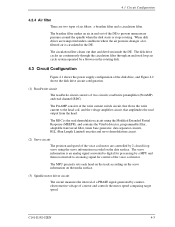
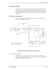
... capture MPU MPU core Position Sense SVC (3) DAC (4) Power Amp VCM current (7) CSR VCM CSR: Current Sense Resister VCM: Voice Coil Motor (5) Spindle motor control (6) Driver Spindle motor Figure 4.6 Block diagram of servo control circuit (1) Microprocessor unit (MPU) The MPU executes startup of the MPU are submitted to the specified cylinder...
... capture MPU MPU core Position Sense SVC (3) DAC (4) Power Amp VCM current (7) CSR VCM CSR: Current Sense Resister VCM: Voice Coil Motor (5) Spindle motor control (6) Driver Spindle motor Figure 4.6 Block diagram of servo control circuit (1) Microprocessor unit (MPU) The MPU executes startup of the MPU are submitted to the specified cylinder...
Manual/User Guide
Page 67
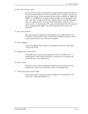
... of the VCM drive current, and the value is converted from digital-to-analog so that an analog output voltage is a power amplitude circuit that indicates the cylinder position, and index information. The servo signals do A/D-convert by converting the VCM current into voltage and feeding back. A spindle driver IC with A-B and...
... of the VCM drive current, and the value is converted from digital-to-analog so that an analog output voltage is a power amplitude circuit that indicates the cylinder position, and index information. The servo signals do A/D-convert by converting the VCM current into voltage and feeding back. A spindle driver IC with A-B and...
Manual/User Guide
Page 72
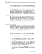
...MPU then feeds the VCM drive current by setting the calculated ...seek operation under the spindle rotates in the motor is used as the spindle motor driver (called SVC hereafter). To position the head at the target cylinder, the track...a counter electromotive force. When the head arrives at the center of a track, the DSP drives the VCM by sending several signals from the host, the MPU confirms the necessity of the...the MPU using a PHASE signal for each sampling time, the VCM drive current is followed. (3) Track following control. The calculation is controlled by feeding micro current...
...MPU then feeds the VCM drive current by setting the calculated ...seek operation under the spindle rotates in the motor is used as the spindle motor driver (called SVC hereafter). To position the head at the target cylinder, the track...a counter electromotive force. When the head arrives at the center of a track, the DSP drives the VCM by sending several signals from the host, the MPU confirms the necessity of the...the MPU using a PHASE signal for each sampling time, the VCM drive current is followed. (3) Track following control. The calculation is controlled by feeding micro current...
Manual/User Guide
Page 208
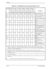
... wait to pause after negating DMARDY-) tIORDYZ 20 20 20 20 20 20 Maximum time before releasing IORDY tZIORDY 0 0 0 0 0 0 Minimum time before driving IORDY (*4) tACK 20 20 20 20 20 20 Setup and hold (tDH, tCH) times in a configuration with one agent (either sender or recipient) is waiting...other agent to respond with minimum (*1) TUI 0 0 0 0 0 0 Unlimited interlock time (*1) tAZ 10 10 10 10 10 10 Maximum time allowed for output drivers to release (from asserted or negated) tZAH 20 20 20 20 20 20 Minimum delay time required for output tZAD...
... wait to pause after negating DMARDY-) tIORDYZ 20 20 20 20 20 20 Maximum time before releasing IORDY tZIORDY 0 0 0 0 0 0 Minimum time before driving IORDY (*4) tACK 20 20 20 20 20 20 Setup and hold (tDH, tCH) times in a configuration with one agent (either sender or recipient) is waiting...other agent to respond with minimum (*1) TUI 0 0 0 0 0 0 Unlimited interlock time (*1) tAZ 10 10 10 10 10 10 Maximum time allowed for output drivers to release (from asserted or negated) tZAH 20 20 20 20 20 20 Minimum delay time required for output tZAD...
Manual/User Guide
Page 243
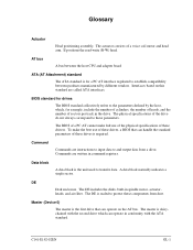
... this standard are written in conformity with the ATA standard. Interfaces based on the AT bus. To make full use of these drives is the unit used to these drivers. Command Commands are instructions to input data to establish compatibility between the host CPU and adapter board ATA (AT Attachment) standard The...
... this standard are written in conformity with the ATA standard. Interfaces based on the AT bus. To make full use of these drives is the unit used to these drivers. Command Commands are instructions to input data to establish compatibility between the host CPU and adapter board ATA (AT Attachment) standard The...


