Manual/User Guide
Page 19
... hardware reset 6-4 Figure 6.3 Response to software reset 6-5 Figure 6.4 Response to diagnostic command 6-6 Figure 6.5 Sector slip processing 6-10 Figure 6.6 Alternate cylinder assignment 6-11 Figure 6.7 Data buffer configuration 6-12 Tables Table 1.1 Table 1.2 Table 1.3 Table 1.4 Table 1.5 Table 1.6 Specifications 1-4 Model names and product numbers 1-5 Current and power dissipation 1-6 Environmental specifications 1-7 Acoustic noise specification 1-8 Shock and vibration...
... hardware reset 6-4 Figure 6.3 Response to software reset 6-5 Figure 6.4 Response to diagnostic command 6-6 Figure 6.5 Sector slip processing 6-10 Figure 6.6 Alternate cylinder assignment 6-11 Figure 6.7 Data buffer configuration 6-12 Tables Table 1.1 Table 1.2 Table 1.3 Table 1.4 Table 1.5 Table 1.6 Specifications 1-4 Model names and product numbers 1-5 Current and power dissipation 1-6 Environmental specifications 1-7 Acoustic noise specification 1-8 Shock and vibration...
Manual/User Guide
Page 25
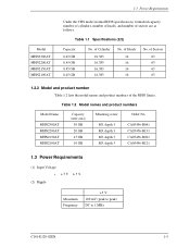
... of the MHN Series. of Sectors 63 63 63 63 1.2.2 Model and product number Table 1.2 lists the model names and product numbers of sectors are as follows. Table 1.2 Model names and product numbers Model Name MHN2300AT MHN2200AT MHN2150AT MHN2100AT Capacity (user area) 30 GB 20 GB 15 GB 10 GB Mounting screw M3, depth 3 M3, depth 3 M3, depth 3 M3, depth...
... of the MHN Series. of Sectors 63 63 63 63 1.2.2 Model and product number Table 1.2 lists the model names and product numbers of sectors are as follows. Table 1.2 Model names and product numbers Model Name MHN2300AT MHN2200AT MHN2150AT MHN2100AT Capacity (user area) 30 GB 20 GB 15 GB 10 GB Mounting screw M3, depth 3 M3, depth 3 M3, depth 3 M3, depth...

Manual/User Guide
Page 34
...spindle motors, actuators, and a circulating air filter. Figure 2.2 illustrates the configuration of the disks and heads of disks used varies with the model, as described below. Numerals 0 to 3 indicate read /write preamplifier, and controller PCA. The inner diameter is not rotating and loads ...while the disk is 20 mm. Device Configuration 2.1 Device Configuration Figure 2.1 shows the disk drive. The disk drive consists of the disk is 65 mm. MHN Series (1) Disk (2) Head Figure 2.1 Disk drive outerview The outer diameter of a disk enclosure (DE), read /write heads. 2-2 C141-...
...spindle motors, actuators, and a circulating air filter. Figure 2.2 illustrates the configuration of the disks and heads of disks used varies with the model, as described below. Numerals 0 to 3 indicate read /write preamplifier, and controller PCA. The inner diameter is not rotating and loads ...while the disk is 20 mm. Device Configuration 2.1 Device Configuration Figure 2.1 shows the disk drive. The disk drive consists of the disk is 65 mm. MHN Series (1) Disk (2) Head Figure 2.1 Disk drive outerview The outer diameter of a disk enclosure (DE), read /write heads. 2-2 C141-...

Manual/User Guide
Page 46
... hit HDD each other. Do not place HDD vertically to avoid falling down. Recommended equipments ESD Shock Contents Wrist strap ESD mat Low shock driver Model JX-1200-3056-8 SKY-8A (Color Seiden Mat) SS-6500 Maker SUMITOMO 3M Achilles HIOS 3-8 C141-E120-02EN Do not stack when carrying. M3 0.49...
... hit HDD each other. Do not place HDD vertically to avoid falling down. Recommended equipments ESD Shock Contents Wrist strap ESD mat Low shock driver Model JX-1200-3056-8 SKY-8A (Color Seiden Mat) SS-6500 Maker SUMITOMO 3M Achilles HIOS 3-8 C141-E120-02EN Do not stack when carrying. M3 0.49...

Manual/User Guide
Page 48
... lines. This is because the interface is designed for ribbon cables and not for the cable connectors. Figure 3.9 Cable connections 3-10 C141-E120-02EN Table 3.2 Cable connector specifications ATA interface and power supply cable (44-pin type) Name Cable socket (44-pin type...) Model 89361-144 Manufacturer BERG IMPORTANT For the host interface cable, use a ribbon cable. Installation Conditions 3.3.2 Cable connector specifications Table 3.2 lists ...
... lines. This is because the interface is designed for ribbon cables and not for the cable connectors. Figure 3.9 Cable connections 3-10 C141-E120-02EN Table 3.2 Cable connector specifications ATA interface and power supply cable (44-pin type) Name Cable socket (44-pin type...) Model 89361-144 Manufacturer BERG IMPORTANT For the host interface cable, use a ribbon cable. Installation Conditions 3.3.2 Cable connector specifications Table 3.2 lists ...
Manual/User Guide
Page 109
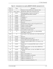
... with IORDY flow control : 120 [ns] Reserved Major version number *9 Minor version number (not reported) Support of command sets *10 Support of command sets *11 Support of 3) Word 23-26 27-46 47 48 49 50 51 52 53 54 55 56 ...(Variable) *6 *2 X'0000' X'xx07' X'0003' X'0078' X'0078' X'00F0' X'0078' X'0000' X'003C' X'0000' X'346B' X'5B08' X'4003' Description Firmware revision (ASCII code, 8 characters, left) Model name (ASCII code, 40 characters, left) Maximum number of sectors per interrupt on READ/WRITE MULTIPLE command Reserved Capabilities *3 Capabilities PIO data transfer mode *4 Reserved...
... with IORDY flow control : 120 [ns] Reserved Major version number *9 Minor version number (not reported) Support of command sets *10 Support of command sets *11 Support of 3) Word 23-26 27-46 47 48 49 50 51 52 53 54 55 56 ...(Variable) *6 *2 X'0000' X'xx07' X'0003' X'0078' X'0078' X'00F0' X'0078' X'0000' X'003C' X'0000' X'346B' X'5B08' X'4003' Description Firmware revision (ASCII code, 8 characters, left) Model name (ASCII code, 40 characters, left) Maximum number of sectors per interrupt on READ/WRITE MULTIPLE command Reserved Capabilities *3 Capabilities PIO data transfer mode *4 Reserved...

