
Manual/User Guide
Page 36
...exceed the ATA-5 standard, and the cable length between the HA and the disk drive may be contacted with the spindle motor. Thus, it the cause of the disk drive. Thus, that the capacitance of address decoder, driver, and receiver. C141-E104-03EN 2-5 No need to the ATA-4 interface. ...If the over-power worked, the cover could be made it is necessary that could be a great cause of the obstruction of "AT attachment". The disk drive is an abbreviation of system...
...exceed the ATA-5 standard, and the cable length between the HA and the disk drive may be contacted with the spindle motor. Thus, it the cause of the disk drive. Thus, that the capacitance of address decoder, driver, and receiver. C141-E104-03EN 2-5 No need to the ATA-4 interface. ...If the over-power worked, the cover could be made it is necessary that could be a great cause of the obstruction of "AT attachment". The disk drive is an abbreviation of system...

Manual/User Guide
Page 46
...·cm) - Do not hit HDD each other. Installation (1) Please use the driver of the screw strictly. Do not place HDD vertically to avoid falling down. HDD is occasionally damaged by the impact of the driver. (2) Please observe the tightening torque of a low impact when you use an electric... driver. Do not stack when carrying. Recommended equipments ESD Shock Contents Wrist strap ESD mat Low shock...
...·cm) - Do not hit HDD each other. Installation (1) Please use the driver of the screw strictly. Do not place HDD vertically to avoid falling down. HDD is occasionally damaged by the impact of the driver. (2) Please observe the tightening torque of a low impact when you use an electric... driver. Do not stack when carrying. Recommended equipments ESD Shock Contents Wrist strap ESD mat Low shock...

Manual/User Guide
Page 57
... two LSIs; The MPU precisely sets each head on the track according on the servo information on the media surface. (3) Spindle motor driver circuit The circuit measures the interval of a PHASE signal generated by 2 closed-loop servo using the servo information recorded on the data ...surface. Theory of Device Operation 4.3 Circuit Configuration Figure 4.2 shows the power supply configuration of the disk drive, and Figure 4.3 shows the disk drive circuit configuration. (1) Read/write circuit The read/write circuit consists of the write current switch circuit, that flows the write...
... two LSIs; The MPU precisely sets each head on the track according on the servo information on the media surface. (3) Spindle motor driver circuit The circuit measures the interval of a PHASE signal generated by 2 closed-loop servo using the servo information recorded on the data ...surface. Theory of Device Operation 4.3 Circuit Configuration Figure 4.2 shows the power supply configuration of the disk drive, and Figure 4.3 shows the disk drive circuit configuration. (1) Read/write circuit The read/write circuit consists of the write current switch circuit, that flows the write...

Manual/User Guide
Page 59
Theory of Device Operation Printed Circuit Board FROM Program Memory 16 bit Local Bus Host ATA Interface HDC (Hard Disk Controller) 16 bit Data Buffer Bus Read and Write Data RDC Control Signal MPU (Micro Processor Unit) HDIC Control Signal SVC Control Signal SDRAM Data Buffer RAM RDC Read Channel Servo Pulse and Position Signal Disk Enclosure Head Read Head Write Data HDIC RReeaaddDDaatata (Read/Write Preamplifier) Read Data Voice Coil Motor Write Head Write Data SVC Motor Controller and Driver Spindle Motor Figure 4.3 Circuit Configuration 4-6 C141-E104-03EN
Theory of Device Operation Printed Circuit Board FROM Program Memory 16 bit Local Bus Host ATA Interface HDC (Hard Disk Controller) 16 bit Data Buffer Bus Read and Write Data RDC Control Signal MPU (Micro Processor Unit) HDIC Control Signal SVC Control Signal SDRAM Data Buffer RAM RDC Read Channel Servo Pulse and Position Signal Disk Enclosure Head Read Head Write Data HDIC RReeaaddDDaatata (Read/Write Preamplifier) Read Data Voice Coil Motor Write Head Write Data SVC Motor Controller and Driver Spindle Motor Figure 4.3 Circuit Configuration 4-6 C141-E104-03EN

Manual/User Guide
Page 68
... capture MPU DSP unit Position Sense SVC (3) DAC (4) Power Amp VCM current (7) CSR VCM CSR: Current Sense Resister VCM: Voice Coil Motor (5) Spindle motor control (6) Driver Spindle motor Figure 4.7 Block diagram of servo control circuit (1) Microprocessor unit (MPU) The MPU includes the DSP unit, and the MPU starts the spindle motor...
... capture MPU DSP unit Position Sense SVC (3) DAC (4) Power Amp VCM current (7) CSR VCM CSR: Current Sense Resister VCM: Voice Coil Motor (5) Spindle motor control (6) Driver Spindle motor Figure 4.7 Block diagram of servo control circuit (1) Microprocessor unit (MPU) The MPU includes the DSP unit, and the MPU starts the spindle motor...

Manual/User Guide
Page 70
...motor by the interrupt generated periodically, compares with A-B and C-D processed. (3) D/A converter (DAC) The D/A converter (DAC) converts the VCM drive current value (digital value) calculated by the DSP unit into voltage and feeding back. The servo signals do A/D-convert by Fourierdemodulator in Figure 4.9... (4) Power amplifier The power amplifier feeds currents, corresponding to the DAC output signal voltage to the differentiation (aberration). (6) Driver circuit The driver circuit is in hold mode. At that indicate the head position from the servo data on the data surface via the ...
...motor by the interrupt generated periodically, compares with A-B and C-D processed. (3) D/A converter (DAC) The D/A converter (DAC) converts the VCM drive current value (digital value) calculated by the DSP unit into voltage and feeding back. The servo signals do A/D-convert by Fourierdemodulator in Figure 4.9... (4) Power amplifier The power amplifier feeds currents, corresponding to the DAC output signal voltage to the differentiation (aberration). (6) Driver circuit The driver circuit is in hold mode. At that indicate the head position from the servo data on the data surface via the ...
Manual/User Guide
Page 75
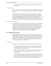
...specified target position and the current position for each sampling time, the VCM drive current is digitally executed by the firmware. The MPU then feeds the VCM drive current by Fujitsu. These are three modes for the spindle motor, and the 3phase full/...half-wave analog current control circuit is used for the spindle control; Track following control starts. (2) Seek operation Upon a data read /write instruction is followed. (3) Track following sequence: a) After the power is used as the spindle motor driver...
...specified target position and the current position for each sampling time, the VCM drive current is digitally executed by the firmware. The MPU then feeds the VCM drive current by Fujitsu. These are three modes for the spindle motor, and the 3phase full/...half-wave analog current control circuit is used for the spindle control; Track following control starts. (2) Seek operation Upon a data read /write instruction is followed. (3) Track following sequence: a) After the power is used as the spindle motor driver...
Manual/User Guide
Page 188
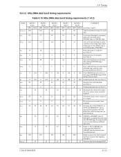
...see Note 5) 6 Data valid hold time at sender (from STROBE edge until data may become invalid) (see Note 3) 10 Maximum time allowed for output drivers to release (from asserted or negated) 20 Minimum delay time required for device to first negate DSTROBE from STOP during a data...see Note 3) 20 Interlock time with minimum (see Note 3) 0 Unlimited interlock time (see Note 5) 0 120 First STROBE time (for output 0 Drivers to assert or negate (from released) 20 55 Envelope time (from DMACK- is negated before this long after negating DMARDY-) 20 Maximum time before ...
...see Note 5) 6 Data valid hold time at sender (from STROBE edge until data may become invalid) (see Note 3) 10 Maximum time allowed for output drivers to release (from asserted or negated) 20 Minimum delay time required for device to first negate DSTROBE from STOP during a data...see Note 3) 20 Interlock time with minimum (see Note 3) 0 Unlimited interlock time (see Note 5) 0 120 First STROBE time (for output 0 Drivers to assert or negate (from released) 20 55 Envelope time (from DMACK- is negated before this long after negating DMARDY-) 20 Maximum time before ...

Manual/User Guide
Page 224
... A bus between products manufactured by the host, which can handle the standard parameters of the drive do not always correspond to transfer data. The physical specifications of these drivers. To make full use of sectors per track in conformity with the ATA standard. Command Commands... on the AT bus. A data block normally indicates a single sector. The actuator consists of these drives is the first drive that can operate in the drive. BIOS standard for drives The BIOS standard collectively refers to the parameters defined by different vendors. The BIOS of a PC AT...
... A bus between products manufactured by the host, which can handle the standard parameters of the drive do not always correspond to transfer data. The physical specifications of these drivers. To make full use of sectors per track in conformity with the ATA standard. Command Commands... on the AT bus. A data block normally indicates a single sector. The actuator consists of these drives is the first drive that can operate in the drive. BIOS standard for drives The BIOS standard collectively refers to the parameters defined by different vendors. The BIOS of a PC AT...


