Manual/User Guide
Page 15
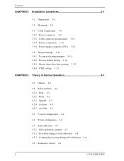
... Conditions 3-1 3.1 Dimensions 3-2 3.2 Mounting 3-4 3.3 Cable Connections 3-9 3.3.1 Device connector 3-9 3.3.2 Cable connector specifications 3-10 3.3.3 Device connection 3-10 3.3.4 Power supply connector (CN1) 3-11 3.4 Jumper Settings 3-11 3.4.1 Location of setting jumpers 3-11 3.4.2 Factory default setting 3-12 3.4.3 Master drive-slave drive setting 3-12 3.4.4 CSEL setting 3-13 CHAPTER 4 Theory of Device Operation 4-1 4.1 Outline 4-2 4.2 Subassemblies 4-2 4.2.1 Disk 4-2 4.2.2 Head 4-2 4.2.3 Spindle 4-3 4.2.4 Actuator 4-3 4.2.5 Air filter 4-3 4.3 Circuit Configuration 4-4 4.4 Power...
... Conditions 3-1 3.1 Dimensions 3-2 3.2 Mounting 3-4 3.3 Cable Connections 3-9 3.3.1 Device connector 3-9 3.3.2 Cable connector specifications 3-10 3.3.3 Device connection 3-10 3.3.4 Power supply connector (CN1) 3-11 3.4 Jumper Settings 3-11 3.4.1 Location of setting jumpers 3-11 3.4.2 Factory default setting 3-12 3.4.3 Master drive-slave drive setting 3-12 3.4.4 CSEL setting 3-13 CHAPTER 4 Theory of Device Operation 4-1 4.1 Outline 4-2 4.2 Subassemblies 4-2 4.2.1 Disk 4-2 4.2.2 Head 4-2 4.2.3 Spindle 4-3 4.2.4 Actuator 4-3 4.2.5 Air filter 4-3 4.3 Circuit Configuration 4-4 4.4 Power...
Manual/User Guide
Page 19
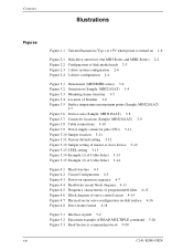
... (Typ.) at +5V when power is turned on 1-6 Figure 2.1 Disk drive outerview (the MHJ Series and MHK Series) 2-2 Figure 2.2 Configuration of disk media heads 2-3 Figure 2.3 1 drive system configuration 2-4 Figure 2.4 2 drives configuration 2-4 Figure 3.1 Dimensions (MHJ/MHK series) 3-2 Figure 3.2 Orientation (Sample...Cable connections 3-10 Figure 3.9 Power supply connector pins (CN1) 3-11 Figure 3.10 Jumper location 3-11 Figure 3.11 Factory default setting 3-12 Figure 3.12 Jumper setting of master or slave device 3-12 Figure 3.13 CSEL setting 3-13 Figure 3.14 Example (1) of Cable Select 3-13...
... (Typ.) at +5V when power is turned on 1-6 Figure 2.1 Disk drive outerview (the MHJ Series and MHK Series) 2-2 Figure 2.2 Configuration of disk media heads 2-3 Figure 2.3 1 drive system configuration 2-4 Figure 2.4 2 drives configuration 2-4 Figure 3.1 Dimensions (MHJ/MHK series) 3-2 Figure 3.2 Orientation (Sample...Cable connections 3-10 Figure 3.9 Power supply connector pins (CN1) 3-11 Figure 3.10 Jumper location 3-11 Figure 3.11 Factory default setting 3-12 Figure 3.12 Jumper setting of master or slave device 3-12 Figure 3.13 CSEL setting 3-13 Figure 3.14 Example (1) of Cable Select 3-13...
Manual/User Guide
Page 38
CHAPTER 3 Installation Conditions 3.1 Dimensions 3.2 Mounting 3.3 Cable Connections 3.4 Jumper Settings This chapter gives the external dimensions, installation conditions, surface temperature conditions, cable connections, and switch settings of the hard disk drives. C141-E088-03EN 3-1
CHAPTER 3 Installation Conditions 3.1 Dimensions 3.2 Mounting 3.3 Cable Connections 3.4 Jumper Settings This chapter gives the external dimensions, installation conditions, surface temperature conditions, cable connections, and switch settings of the hard disk drives. C141-E088-03EN 3-1
Manual/User Guide
Page 48
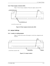
3.4 Jumper Settings 3.3.4 Power supply connector (CN1) Figure 3.9 shows the pin assignment of the jumpers to select drive configuration and functions. Figure 3.9 Power supply connector pins (CN1) 3.4 Jumper Settings 3.4.1 Location of setting jumpers Figure 3.10 shows the location of the power supply connector (CN1). Figure 3.10 Jumper location C141-E088-03EN 3-11
3.4 Jumper Settings 3.3.4 Power supply connector (CN1) Figure 3.9 shows the pin assignment of the jumpers to select drive configuration and functions. Figure 3.9 Power supply connector pins (CN1) 3.4 Jumper Settings 3.4.1 Location of setting jumpers Figure 3.10 shows the location of the power supply connector (CN1). Figure 3.10 Jumper location C141-E088-03EN 3-11
Manual/User Guide
Page 49
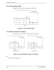
Open 1 CA 2 DB Open (a) Master drive 1 CA Open Short 2 DB (b) Slave drive Figure 3.12 Jumper setting of master or slave device Note: Pins A and C should be open. 3-12 C141-E088-03EN Open Figure 3.11 Factory default setting 3.4.3 Master drive-slave drive setting Master device (device #0) or slave device (device #1) is selected. Installation Conditions 3.4.2 Factory default setting Figure 3.11 shows the default setting position at the factory.
Open 1 CA 2 DB Open (a) Master drive 1 CA Open Short 2 DB (b) Slave drive Figure 3.12 Jumper setting of master or slave device Note: Pins A and C should be open. 3-12 C141-E088-03EN Open Figure 3.11 Factory default setting 3.4.3 Master drive-slave drive setting Master device (device #0) or slave device (device #1) is selected. Installation Conditions 3.4.2 Factory default setting Figure 3.11 shows the default setting position at the factory.
Manual/User Guide
Page 50
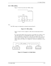
... connected to the CSEL conductor, the CSEL is not depended on setting between pins Band D. 3.4.4 CSEL setting Figure 3.13 shows the cable select (CSEL) setting. 3.4 Jumper Settings Open 1 CA 2 DB Short Note: The CSEL setting is set to low level. Figure 3.14 Example (1) of the cable and connecting it to ground...
... connected to the CSEL conductor, the CSEL is not depended on setting between pins Band D. 3.4.4 CSEL setting Figure 3.13 shows the cable select (CSEL) setting. 3.4 Jumper Settings Open 1 CA 2 DB Short Note: The CSEL setting is set to low level. Figure 3.14 Example (1) of the cable and connecting it to ground...

Manual/User Guide
Page 111
is a level higher than VIL. Bits 12-8: In the case of Device 1 (slave drive), a valid value is set . Bit 8: Reserved Bits 7-0: In the case of 8) Bit 1 = '1': Mode 1 Bit 0 = '1': Mode 0 *15 WORD 93 Bits 15-14: Reserved ... the selfdiagnosis. of Device 1. '00' = Reserved '01' = Using a jumper. '10' = Using the CSEL signal. '11' = Other method. Bit 3: '1' = Device 0, an error was detected. was detected. Interface Table 5.4 Information to be read by IDENTIFY DEVICE command (7 of Device 0 (master drive), a valid value is set . Bit 7: Reserved Bit 6: '1' = Device ...
is a level higher than VIL. Bits 12-8: In the case of Device 1 (slave drive), a valid value is set . Bit 8: Reserved Bits 7-0: In the case of 8) Bit 1 = '1': Mode 1 Bit 0 = '1': Mode 0 *15 WORD 93 Bits 15-14: Reserved ... the selfdiagnosis. of Device 1. '00' = Reserved '01' = Using a jumper. '10' = Using the CSEL signal. '11' = Other method. Bit 3: '1' = Device 0, an error was detected. was detected. Interface Table 5.4 Information to be read by IDENTIFY DEVICE command (7 of Device 0 (master drive), a valid value is set . Bit 7: Reserved Bit 6: '1' = Device ...
Manual/User Guide
Page 221
... example of READ MULTIPLE command 5-20 Execution timing of self-calibration 4-8 External magnetic field 3-6 F Factory default setting 3-12 Failure prediction capability flag 5-65 Feature register function 5-58 Feature register value 5-40, 5-58 Features 1-2 Features register ... Interface 1-3, 5-1 Interface signal 5-2 Invalidating caching data 6-15 J Jumper location 3-11 Jumper setting 3-11 L Large capacity 1-2 LBA mode 6-9 Limitation of mounting 3-5 Logical address 6-8 Logical interface 5-6 M Master 1-3 Master drive setting 3-12 Master password 5-74 Mean time between failures 1-9 C141-E088-03EN
... example of READ MULTIPLE command 5-20 Execution timing of self-calibration 4-8 External magnetic field 3-6 F Factory default setting 3-12 Failure prediction capability flag 5-65 Feature register function 5-58 Feature register value 5-40, 5-58 Features 1-2 Features register ... Interface 1-3, 5-1 Interface signal 5-2 Invalidating caching data 6-15 J Jumper location 3-11 Jumper setting 3-11 L Large capacity 1-2 LBA mode 6-9 Limitation of mounting 3-5 Logical address 6-8 Logical interface 5-6 M Master 1-3 Master drive setting 3-12 Master password 5-74 Mean time between failures 1-9 C141-E088-03EN

