Manual/User Guide
Page 19
... 3.11 Factory default setting 3-12 Figure 3.12 Jumper setting of master or slave device 3-12 Figure 3.13 CSEL setting 3-13 Figure 3.14 Example (1) of Cable Select 3-13 Figure 3.15 Example (2) of Cable Select 3-14 Figure 4.1 Head structure 4-3 Figure 4.2 Circuit Configuration 4-5 Figure 4.3 Power-on operation sequence 4-7 Figure 4.4 Read/write circuit block diagram 4-11 Figure 4.5 Frequency characteristic of programmable filter 4-12 Figure 4.6 Block diagram of servo control circuit 4-14 Figure 4.7 Physical sector servo configuration on disk surface 4-16 Figure 4.8 Servo frame format...
... 3.11 Factory default setting 3-12 Figure 3.12 Jumper setting of master or slave device 3-12 Figure 3.13 CSEL setting 3-13 Figure 3.14 Example (1) of Cable Select 3-13 Figure 3.15 Example (2) of Cable Select 3-14 Figure 4.1 Head structure 4-3 Figure 4.2 Circuit Configuration 4-5 Figure 4.3 Power-on operation sequence 4-7 Figure 4.4 Read/write circuit block diagram 4-11 Figure 4.5 Frequency characteristic of programmable filter 4-12 Figure 4.6 Block diagram of servo control circuit 4-14 Figure 4.7 Physical sector servo configuration on disk surface 4-16 Figure 4.8 Servo frame format...
Manual/User Guide
Page 30
... not include power supply abnormalities during disk media initialization (formatting) or processing of the DE surface temperature. Also the operating conditions except the environment temperature are based on the MTBF conditions. (4) Data assurance in the event of power failure Except for the data block being written to, the data on time 50/day or less Total 50,000 or less 1/day or more needed. 5 to...
... not include power supply abnormalities during disk media initialization (formatting) or processing of the DE surface temperature. Also the operating conditions except the environment temperature are based on the MTBF conditions. (4) Data assurance in the event of power failure Except for the data block being written to, the data on time 50/day or less Total 50,000 or less 1/day or more needed. 5 to...

Manual/User Guide
Page 31
... no more than 10 times in the error rate count below. Alternate sectors are not included in 107 seek operations. 1.9 Media Defects Defective sectors are formatted prior to be accessed are evenly distributed on the disk media. (1) Unrecoverable read retries of 1014 bits. The user need not be recovered by the disk drive. It is assumed that the data blocks to shipment from the factory (low level...
... no more than 10 times in the error rate count below. Alternate sectors are not included in 107 seek operations. 1.9 Media Defects Defective sectors are formatted prior to be accessed are evenly distributed on the disk media. (1) Unrecoverable read retries of 1014 bits. The user need not be recovered by the disk drive. It is assumed that the data blocks to shipment from the factory (low level...
Manual/User Guide
Page 49
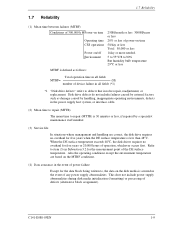
Open Figure 3.11 Factory default setting 3.4.3 Master drive-slave drive setting Master device (device #0) or slave device (device #1) is selected. Open 1 CA 2 DB Open (a) Master drive 1 CA Open Short 2 DB (b) Slave drive Figure 3.12 Jumper setting of master or slave device Note: Pins A and C should be open. 3-12 C141-E088-03EN Installation Conditions 3.4.2 Factory default setting Figure 3.11 shows the default setting position at the factory.
Open Figure 3.11 Factory default setting 3.4.3 Master drive-slave drive setting Master device (device #0) or slave device (device #1) is selected. Open 1 CA 2 DB Open (a) Master drive 1 CA Open Short 2 DB (b) Slave drive Figure 3.12 Jumper setting of master or slave device Note: Pins A and C should be open. 3-12 C141-E088-03EN Installation Conditions 3.4.2 Factory default setting Figure 3.11 shows the default setting position at the factory.

Manual/User Guide
Page 71
... time, the VCM drive current is controlled by Fujitsu. There are digitally controlled by itself, and changes the phase of the current flowed in the motor in the spindle motor. Then, a current (approx. 0.7 A) flows into the D/A converter. For each sampling timing during head movement to the SVC. Theory of Device Operation d) If the head is issued, the MPU seeks the desired track. If a read /write...
... time, the VCM drive current is controlled by Fujitsu. There are digitally controlled by itself, and changes the phase of the current flowed in the motor in the spindle motor. Then, a current (approx. 0.7 A) flows into the D/A converter. For each sampling timing during head movement to the SVC. Theory of Device Operation d) If the head is issued, the MPU seeks the desired track. If a read /write...

Manual/User Guide
Page 79
... the DMACK signal. The device asserts this signal when the device completes the preparation of sector/track)] + (Sector No.) − 1 5-6 C141-E088-03EN signals are LBA bits. and CS1- Note: "I +5 VDC power supplying to the host. When there is not changed. The IDENTIFY DEVICE information indicates whether the device supports the LBA mode. LBA = [((Cylinder No.) × (Number of head) + (Head No.)) × (Number of DMA data transfer to the host system...
... the DMACK signal. The device asserts this signal when the device completes the preparation of sector/track)] + (Sector No.) − 1 5-6 C141-E088-03EN signals are LBA bits. and CS1- Note: "I +5 VDC power supplying to the host. When there is not changed. The IDENTIFY DEVICE information indicates whether the device supports the LBA mode. LBA = [((Cylinder No.) × (Number of head) + (Head No.)) × (Number of DMA data transfer to the host system...

Manual/User Guide
Page 88
... POWER MODE 1 0 0 1 1 0 0 0 NNNND 11100101 SMART 1 0 1 1 0 0 0 0 YYYYD SECURITY DISABLE PASSWORD 1 1 1 1 0 1 1 0 N N N N D SECURITY ERASE PREPARE 1 1 1 1 0 0 1 1 NNNND SECURITY ERASE UNIT 1 1 1 1 0 1 0 0 NNNND SECURITY FREEZE LOCK 1 1 1 1 0 1 0 1 NNNND SECURITY SET PASSWORD 1 1 1 1 0 0 0 1 NNNND SECURITY UNLOCK 1 1 1 1 0 0 1 0 NNNND FLUSH CACHE 1 1 1 0 0 1 1 1 NNNND Notes: FR: Features Register CY: Cylinder Registers SC: Sector Count Register DH: Drive/Head Register SN: Sector Number Register R: Retry at error 1 = Without retry 0 = With retry Y: Necessary to set parameters...
... POWER MODE 1 0 0 1 1 0 0 0 NNNND 11100101 SMART 1 0 1 1 0 0 0 0 YYYYD SECURITY DISABLE PASSWORD 1 1 1 1 0 1 1 0 N N N N D SECURITY ERASE PREPARE 1 1 1 1 0 0 1 1 NNNND SECURITY ERASE UNIT 1 1 1 1 0 1 0 0 NNNND SECURITY FREEZE LOCK 1 1 1 1 0 1 0 1 NNNND SECURITY SET PASSWORD 1 1 1 1 0 0 0 1 NNNND SECURITY UNLOCK 1 1 1 1 0 0 1 0 NNNND FLUSH CACHE 1 1 1 0 0 1 1 1 NNNND Notes: FR: Features Register CY: Cylinder Registers SC: Sector Count Register DH: Drive/Head Register SN: Sector Number Register R: Retry at error 1 = Without retry 0 = With retry Y: Necessary to set parameters...

Manual/User Guide
Page 90
... error, irrespective of the command execution, command block registers contain the cylinder, head, and sector addresses (in the CHS mode) or logical block address (in maximum. When the L bit is not on the track specified by the host, the device performs a implied seek. Upon the completion of the R bit setting. C141-E088-03EN 5-17 After the head reaches to data transfer, see Subsection 5.4.1. Number of sectors...
... error, irrespective of the command execution, command block registers contain the cylinder, head, and sector addresses (in the CHS mode) or logical block address (in maximum. When the L bit is not on the track specified by the host, the device performs a implied seek. Upon the completion of the R bit setting. C141-E088-03EN 5-17 After the head reaches to data transfer, see Subsection 5.4.1. Number of sectors...
Manual/User Guide
Page 96
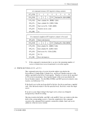
... device performs a implied seek. For the DRQ, INTRQ, and BSY protocols related to the the specified track, the device writes the target sector. After the head reaches to data transfer, see Subsection 5.4.2. If an error occurs when writing to the target sector, retries are written to the data field of the corresponding sector(s). If the head is set in this register. (5) WRITE SECTOR(S) (X'30' or X'31') This command writes data of...
... device performs a implied seek. For the DRQ, INTRQ, and BSY protocols related to the the specified track, the device writes the target sector. After the head reaches to data transfer, see Subsection 5.4.2. If an error occurs when writing to the target sector, retries are written to the data field of the corresponding sector(s). If the head is set in this register. (5) WRITE SECTOR(S) (X'30' or X'31') This command writes data of...
Manual/User Guide
Page 106
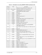
... READ/WRITE MULTIPLE command Reserved Capabilities *3 Reserved PIO data transfer mode *4 Reserved Enable/disable setting of words 54-58 and 64-70, 88 *5 Number of current Cylinders Number of current Head Number of current sectors per track Total number of current sectors Transfer sector count currently set by IDENTIFY DEVICE command (2 of command sets/function C141-E088-03EN 5-33 5.3 Host Commands Table 5.4 Information to be read by READ/WRITE MULTIPLE command *6 Total number of user addressable sectors (LBA mode only) *2 Reserved Multiword DMA transfer mode *7 Advance PIO transfer mode...
... READ/WRITE MULTIPLE command Reserved Capabilities *3 Reserved PIO data transfer mode *4 Reserved Enable/disable setting of words 54-58 and 64-70, 88 *5 Number of current Cylinders Number of current Head Number of current sectors per track Total number of current sectors Transfer sector count currently set by IDENTIFY DEVICE command (2 of command sets/function C141-E088-03EN 5-33 5.3 Host Commands Table 5.4 Information to be read by READ/WRITE MULTIPLE command *6 Total number of user addressable sectors (LBA mode only) *2 Reserved Multiword DMA transfer mode *7 Advance PIO transfer mode...
Manual/User Guide
Page 109
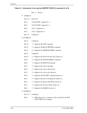
... Supports the power management feature set . Bit 2: '1' = Supports the Removable Media feature set . Interface Table 5.4 Information to be read cache function. Bit 12: '1' = Supports the WRITE BUFFER command. Bit 8: '1' = Supports the SERVICE interrupt. Bit 0: '1' = Supports the SMART feature set . Bit 11: Undefined Bit 10: '1' = Supports the Host Protected Area feature set . Bit 6: '1' = Supports the read by the SET FEATURES sub-command. 5-36 C141-E088-03EN Bit 4: '1' = Supports the PACKET command feature set . Bit 1: '1' = Supports the Security Mode feature set...
... Supports the power management feature set . Bit 2: '1' = Supports the Removable Media feature set . Interface Table 5.4 Information to be read cache function. Bit 12: '1' = Supports the WRITE BUFFER command. Bit 8: '1' = Supports the SERVICE interrupt. Bit 0: '1' = Supports the SMART feature set . Bit 11: Undefined Bit 10: '1' = Supports the Host Protected Area feature set . Bit 6: '1' = Supports the read by the SET FEATURES sub-command. 5-36 C141-E088-03EN Bit 4: '1' = Supports the PACKET command feature set . Bit 1: '1' = Supports the Security Mode feature set...

Manual/User Guide
Page 113
... this command, the device sets the BSY bit of the Sector Count register. (Details are given later.) Enables the advanced power management function. Table 5.5 lists the available values and operational modes that is invalid, the device posts an ABORTED COMMAND error. Transfer mode depends on default settings after hardware reset, the default mode is the same as that may have been modified to a new value since power-on or after software reset. Disables...
... this command, the device sets the BSY bit of the Sector Count register. (Details are given later.) Enables the advanced power management function. Table 5.5 lists the available values and operational modes that is invalid, the device posts an ABORTED COMMAND error. Transfer mode depends on default settings after hardware reset, the default mode is the same as that may have been modified to a new value since power-on or after software reset. Disables...

Manual/User Guide
Page 116
... SET FEATURES command. The mode established before software reset is issued are listed below. If disable default has not been defined after hardware reset, the READ MULTIPLE and WRITE MULTIPLE command operation are posted to be read) 1F7H(ST) 1F6H(DH) 1F5H(CH) 1F4 (CL) H 1F3H(SN) 1F2 (SC) H 1F1H(ER) Status information × × × DV xx xx xx xx Sector count/block Error information After power...
... SET FEATURES command. The mode established before software reset is issued are listed below. If disable default has not been defined after hardware reset, the READ MULTIPLE and WRITE MULTIPLE command operation are posted to be read) 1F7H(ST) 1F6H(DH) 1F5H(CH) 1F4 (CL) H 1F3H(SN) 1F2 (SC) H 1F1H(ER) Status information × × × DV xx xx xx xx Sector count/block Error information After power...

Manual/User Guide
Page 117
... interrupt by the user to be transferred per interrupt by this command becomes invalid when the power is turned on and the occurrence of a hard reset, the host can be set in LBA or CHS mode. If an attempt is made to perform a read or write operation for number of sectors that can issue this command only once when VV bit = 1. The READ MULTIPLE and WRITE MULTIPLE commands are disabled.
... interrupt by the user to be transferred per interrupt by this command becomes invalid when the power is turned on and the occurrence of a hard reset, the host can be set in LBA or CHS mode. If an attempt is made to perform a read or write operation for number of sectors that can issue this command only once when VV bit = 1. The READ MULTIPLE and WRITE MULTIPLE commands are disabled.

Manual/User Guide
Page 142
.... Although this command while in Table 5.12 to the device. Issuing this command invalidates the user password, the master password is returned. The host transfers the 512-byte data shown in LOCKED MODE or FROZEN MODE returns the Aborted Command error. (The section about the SECURITY FREEZE LOCK command describes LOCKED MODE and FROZEN MODE.) C141-E088-03EN 5-69 To recover the master password, issue the SECURITY SET PASSWORD command and reset the user password. If the user password or master password transferred from the...
.... Although this command while in Table 5.12 to the device. Issuing this command invalidates the user password, the master password is returned. The host transfers the 512-byte data shown in LOCKED MODE or FROZEN MODE returns the Aborted Command error. (The section about the SECURITY FREEZE LOCK command describes LOCKED MODE and FROZEN MODE.) C141-E088-03EN 5-69 To recover the master password, issue the SECURITY SET PASSWORD command and reset the user password. If the user password or master password transferred from the...

Manual/User Guide
Page 147
... The lock function is enabled after the device is turned off and then on . LOCKED MODE can be set cannot cancel LOCKED MODE. The host transfers the 512-byte data shown in LOCKED MODE or FROZEN MODE returns the Aborted Command error. The lock function is saved as a new user password. The specified password is not enabled. The device determines the operation of the lock function according to 15 Reserved Password (32 bytes) Master password version number Reserved...
... The lock function is enabled after the device is turned off and then on . LOCKED MODE can be set cannot cancel LOCKED MODE. The host transfers the 512-byte data shown in LOCKED MODE or FROZEN MODE returns the Aborted Command error. The lock function is saved as a new user password. The specified password is not enabled. The device determines the operation of the lock function according to 15 Reserved Password (32 bytes) Master password version number Reserved...

Manual/User Guide
Page 148
...) 1F1 (ER) h Status information × × × DV xx xx xx xx xx Error information (35) SECURITY UNLOCK This command cancels LOCKED MODE. If the password comparison fails, the device decrements the UNLOCK counter. If the passwords are the same, LOCKED MODE is returned. The host transfers the 512-byte data shown in LOCKED MODE is set to the device. Operation of five. Otherwise, the Aborted Command error is compared with the master password already set .
...) 1F1 (ER) h Status information × × × DV xx xx xx xx xx Error information (35) SECURITY UNLOCK This command cancels LOCKED MODE. If the password comparison fails, the device decrements the UNLOCK counter. If the passwords are the same, LOCKED MODE is returned. The host transfers the 512-byte data shown in LOCKED MODE is set to the device. Operation of five. Otherwise, the Aborted Command error is compared with the master password already set .

Manual/User Guide
Page 201
... example where (physical) sector 5 is assigned to the subsequent normal sector (physically adjacent sector to physical sector 5 is specified, the device accesses physical sector 6 instead of spare area are provided for every physical head. 1) Spare cylinder for sector slip: used for alternating defective sectors at formatting in shipment (4 cylinders) 2) Spare cylinder for alternative assignment: used for automatic alternative assignment at read error occurrence. (4 cylinders) 6.4.2 Alternating defective sectors The two alternating...
... example where (physical) sector 5 is assigned to the subsequent normal sector (physically adjacent sector to physical sector 5 is specified, the device accesses physical sector 6 instead of spare area are provided for every physical head. 1) Spare cylinder for sector slip: used for alternating defective sectors at formatting in shipment (4 cylinders) 2) Spare cylinder for alternative assignment: used for automatic alternative assignment at read error occurrence. (4 cylinders) 6.4.2 Alternating defective sectors The two alternating...

Manual/User Guide
Page 220
... sector 6-12 Ambient temperature 3-7 ATA 2-5 ATA interface 2-4 Attribute ID 5-63 Attribute value for worst case so far 5-64 Automatic alternate assignment 6-13 Average positioning time 1-2 B Block diagram of servo control circuit 4-14 Blower 4-3 Blower effect 2-3 Breather filter 4-3 BSY 5-11 C Cable connection 3-8, 3-9 Cable connector specification 3-10 Caching operation 6-14 Calibration 4-15 CHECK POWER MODE 5-56 Check sum 5-66 C141-E088-03EN CHS mode 6-8 Circuit configuration 4-4, 4-5 Circulation filter 2-3, 4-3 Combination of Identifier and Security level 5-4 Command...
... sector 6-12 Ambient temperature 3-7 ATA 2-5 ATA interface 2-4 Attribute ID 5-63 Attribute value for worst case so far 5-64 Automatic alternate assignment 6-13 Average positioning time 1-2 B Block diagram of servo control circuit 4-14 Blower 4-3 Blower effect 2-3 Breather filter 4-3 BSY 5-11 C Cable connection 3-8, 3-9 Cable connector specification 3-10 Caching operation 6-14 Calibration 4-15 CHECK POWER MODE 5-56 Check sum 5-66 C141-E088-03EN CHS mode 6-8 Circuit configuration 4-4, 4-5 Circulation filter 2-3, 4-3 Combination of Identifier and Security level 5-4 Command...
Manual/User Guide
Page 221
... 4-3 Head structure 4-3 High-speed transfer rate 1-2 Hit all 6-20 Host command 5-13 I IDENTIFY DEVICE 5-31 IDENTIFY DEVICE DMA 5-39 IDLE 5-51 IDLE IMMEDIATE 5-53 Idle mode 6-10 INITIALIZE DEVICE PARAMETERS 5-30 Inner guard band 4-18 Input voltage 1-5 Installation condition 3-1 Insurance failure threshold 5-66 Interface 1-3, 5-1 Interface signal 5-2 Invalidating caching data 6-15 J Jumper location 3-11 Jumper setting 3-11 L Large capacity 1-2 LBA mode 6-9 Limitation of mounting 3-5 Logical address 6-8 Logical interface 5-6 M Master 1-3 Master drive setting 3-12 Master password 5-74 Mean time...
... 4-3 Head structure 4-3 High-speed transfer rate 1-2 Hit all 6-20 Host command 5-13 I IDENTIFY DEVICE 5-31 IDENTIFY DEVICE DMA 5-39 IDLE 5-51 IDLE IMMEDIATE 5-53 Idle mode 6-10 INITIALIZE DEVICE PARAMETERS 5-30 Inner guard band 4-18 Input voltage 1-5 Installation condition 3-1 Insurance failure threshold 5-66 Interface 1-3, 5-1 Interface signal 5-2 Invalidating caching data 6-15 J Jumper location 3-11 Jumper setting 3-11 L Large capacity 1-2 LBA mode 6-9 Limitation of mounting 3-5 Logical address 6-8 Logical interface 5-6 M Master 1-3 Master drive setting 3-12 Master password 5-74 Mean time...


