Manual
Page 1
Z68A-S Series Motherboard User's Manual
Z68A-S Series Motherboard User's Manual
Manual
Page 2
... you will help you to use motherboard better, and tells you purchased this product is the intellectual property of Foxconn, Inc. All images are for reference only, please refer to the physical motherboard for Z68A-S Series motherboard Symbol description: ! CAUTION Statement: ...This manual is disposed of correctly, you want more detailed information about our products, please visit Foxconn's website: http://www.foxconnchannel.com © All ...
... you will help you to use motherboard better, and tells you purchased this product is the intellectual property of Foxconn, Inc. All images are for reference only, please refer to the physical motherboard for Z68A-S Series motherboard Symbol description: ! CAUTION Statement: ...This manual is disposed of correctly, you want more detailed information about our products, please visit Foxconn's website: http://www.foxconnchannel.com © All ...

Manual
Page 3
... information technology equipment ■ EN 61000-3-2/:2000 Electromagnetic compatibility (EMC) Part 3: Limits Section 2: Limits for harmonic current emissions (equipment input current declares that the product Motherboard Z68A-S is in conformity with (reference to the specification under which conformity is declared in accordance with 89/336 EEC-EMC Directive) ■ EN 55022: 1998...
... information technology equipment ■ EN 61000-3-2/:2000 Electromagnetic compatibility (EMC) Part 3: Limits Section 2: Limits for harmonic current emissions (equipment input current declares that the product Motherboard Z68A-S is in conformity with (reference to the specification under which conformity is declared in accordance with 89/336 EEC-EMC Directive) ■ EN 55022: 1998...

Manual
Page 4
...92835 714-738-8868 714-738-8838 Equipment Classification: Type of conformity Trade Name: Model Name: Responsible Party: Address: Telephone: Facsimile: FOXCONN Z68A-S PCE Industry Inc. 458 E. Lambert Rd. Operation is subject to comply with Part 15 of the FCC Rules. Tested to the ...Date : 2011 Supplementary Information: This device complies with FCC standards. Declaration of Product: Manufacturer: Address: FCC Class B Subassembly Motherboard HON HAI PRECISION INDUSTRY COMPANY LTD 66 , CHUNG SHAN RD., TU-CHENG INDUSTRIAL DISTRICT, TAIPEI HSIEN, TAIWAN, R.O.C.
...92835 714-738-8868 714-738-8838 Equipment Classification: Type of conformity Trade Name: Model Name: Responsible Party: Address: Telephone: Facsimile: FOXCONN Z68A-S PCE Industry Inc. 458 E. Lambert Rd. Operation is subject to comply with Part 15 of the FCC Rules. Tested to the ...Date : 2011 Supplementary Information: This device complies with FCC standards. Declaration of Product: Manufacturer: Address: FCC Class B Subassembly Motherboard HON HAI PRECISION INDUSTRY COMPANY LTD 66 , CHUNG SHAN RD., TU-CHENG INDUSTRIAL DISTRICT, TAIPEI HSIEN, TAIWAN, R.O.C.

Manual
Page 5
...DC power supply is any metal leads or connec- Also, make sure there are no leftover screws or metal components placed on the motherboard or within the computer casing. ■ If you are uncertain about any installation steps or have a problem related to the use ... current that your system can operate normally when your electronic equipment. Never turn on the overclocking capac- Incorrect connections might damage the motherboard. ■ When handling the motherboard, avoid touching any , when connecting USB, audio, 1394a, RS232 COM, IrDA or S/PDIF cables to come in your device....
...DC power supply is any metal leads or connec- Also, make sure there are no leftover screws or metal components placed on the motherboard or within the computer casing. ■ If you are uncertain about any installation steps or have a problem related to the use ... current that your system can operate normally when your electronic equipment. Never turn on the overclocking capac- Incorrect connections might damage the motherboard. ■ When handling the motherboard, avoid touching any , when connecting USB, audio, 1394a, RS232 COM, IrDA or S/PDIF cables to come in your device....

Manual
Page 8
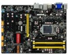
Foxconn products are engineered to unleash more power from your computer. This chapter includes the following information: ■ Product Specifications ■ Layout ■ Back Panel Connectors With advanced overclocking capability and a range of connectivity features for break-through performance. Thank you to maximize computing power, providing only what you need for today multi-media computing requirements, Z68A-S enables you for buying Foxconn Z68A-S motherboard.
Foxconn products are engineered to unleash more power from your computer. This chapter includes the following information: ■ Product Specifications ■ Layout ■ Back Panel Connectors With advanced overclocking capability and a range of connectivity features for break-through performance. Thank you to maximize computing power, providing only what you need for today multi-media computing requirements, Z68A-S enables you for buying Foxconn Z68A-S motherboard.

Manual
Page 11
... Header 18. CD_IN Connector 8. TPM Connector 12. MFG Jumper 16. Speaker Connector 19. LGA 1155 CPU Socket Note : The above motherboard layout is for reference only, please refer to the physical motherboard for detail. 4 PCI Express x16 Slot 4. SYS_FAN1 Header 3. Chassis Intrusion Alarm Header 15. SATA Connectors 17. DDR3 DIMM Slots 22...
... Header 18. CD_IN Connector 8. TPM Connector 12. MFG Jumper 16. Speaker Connector 19. LGA 1155 CPU Socket Note : The above motherboard layout is for reference only, please refer to the physical motherboard for detail. 4 PCI Express x16 Slot 4. SYS_FAN1 Header 3. Chassis Intrusion Alarm Header 15. SATA Connectors 17. DDR3 DIMM Slots 22...

Manual
Page 14
Caution should be exercised during the installation of jumpers. Please refer to the motherboard layout prior to any installation and read the contents in this chapter carefully. CPU Support List: http://www.foxconnsupport.com/cpusupportlist.aspx Memory, VGA Compatibility ... the Memory ■ Install an Expansion Card ■ Install other Internal Connectors ■ Jumper Please visit the following website for more supporting information about your motherboard.
Caution should be exercised during the installation of jumpers. Please refer to the motherboard layout prior to any installation and read the contents in this chapter carefully. CPU Support List: http://www.foxconnsupport.com/cpusupportlist.aspx Memory, VGA Compatibility ... the Memory ■ Install an Expansion Card ■ Install other Internal Connectors ■ Jumper Please visit the following website for more supporting information about your motherboard.
Manual
Page 15
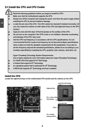
...174; CPU that supports HT Technology ■ A chipset that supports HT Technology ■ An operating system that is not recommended that the motherboard supports the CPU. ■ Always turn on the surface of the CPU may occur. ■ Set the CPU host frequency in accordance with... 8 The CPU cannot be set the frequency beyond hardware specifications since it enabled Install the CPU Locate the alignment keys on the motherboard CPU socket and the notches on the CPU. Read the following guidelines before installing the CPU to your hardware specifications including the CPU...
...174; CPU that supports HT Technology ■ A chipset that supports HT Technology ■ An operating system that is not recommended that the motherboard supports the CPU. ■ Always turn on the surface of the CPU may occur. ■ Set the CPU host frequency in accordance with... 8 The CPU cannot be set the frequency beyond hardware specifications since it enabled Install the CPU Locate the alignment keys on the motherboard CPU socket and the notches on the CPU. Read the following guidelines before installing the CPU to your hardware specifications including the CPU...

Manual
Page 17
...the surface of arrow (counterclockwise). 2. Inadequately removing the CPU cooler may adhere to its default position. ! Check the solder side of the motherboard, push them straight down from motherboard : 1.Turning the push pin (bolt) along with the direction of CPU. 2. Use extreme care when removing the CPU cooler because the ... grease may damage the CPU. 10 10 Place the four bolts of the CPU cooler to correctly install the CPU cooler on the motherboard. 2 CAUTION 1. Pull the push pin straight up. 3. Install the CPU Cooler Follow the steps below to the holes of the...
...the surface of arrow (counterclockwise). 2. Inadequately removing the CPU cooler may adhere to its default position. ! Check the solder side of the motherboard, push them straight down from motherboard : 1.Turning the push pin (bolt) along with the direction of CPU. 2. Use extreme care when removing the CPU cooler because the ... grease may damage the CPU. 10 10 Place the four bolts of the CPU cooler to correctly install the CPU cooler on the motherboard. 2 CAUTION 1. Pull the push pin straight up. 3. Install the CPU Cooler Follow the steps below to the holes of the...
Manual
Page 18
... brand, speed, and chips be used and please select dual channel first to install the memory : ■ Make sure that the motherboard supports the memory. Single Channel - - It is recommended that memory of DIMM modules are unable to prevent hardware damage. ■ ... has two memory sockets as following guidelines before installing the memory to insert the memory, switch the direction. Dual Channel Memory Configuration This motherboard provides four DDR3 memory sockets and supports Dual Channel Technology. DS/SS Dual Channel - Read the following : Channel 0 : DIMM1, DIMM2...
... brand, speed, and chips be used and please select dual channel first to install the memory : ■ Make sure that the motherboard supports the memory. Single Channel - - It is recommended that memory of DIMM modules are unable to prevent hardware damage. ■ ... has two memory sockets as following guidelines before installing the memory to insert the memory, switch the direction. Dual Channel Memory Configuration This motherboard provides four DDR3 memory sockets and supports Dual Channel Technology. DS/SS Dual Channel - Read the following : Channel 0 : DIMM1, DIMM2...

Manual
Page 19
..., make sure to turn off the computer and unplug the power cord from the power outlet to prevent damage to install DDR3 DIMMs on this motherboard.
..., make sure to turn off the computer and unplug the power cord from the power outlet to prevent damage to install DDR3 DIMMs on this motherboard.

Manual
Page 20
... from the chassis back panel. 2. Turn on your operating system. Install the driver provided with a screw. 5. CAUTION 2 2-3 Install an Expansion Card ! ■ Make sure the motherboard supports the expansion card. Make sure the metal contacts on the card until it is locked by the latch at the end of the PCI...
... from the chassis back panel. 2. Turn on your operating system. Install the driver provided with a screw. 5. CAUTION 2 2-3 Install an Expansion Card ! ■ Make sure the motherboard supports the expansion card. Make sure the metal contacts on the card until it is locked by the latch at the end of the PCI...

Manual
Page 21
... are using a 24-pin power supply. We recommend you using a 20-pin power supply, you are properly aligned with the connector on the motherboard. Firmly plug the power supply cable into the connector and make sure all the devices have been installed properly before applying the power supply. 24... 24 13 10 +12V 22 +5V 11 +12V 23 +5V 12 PWR1 1 12 3.3V 24 GND ! 2 CAUTION 2-4 Install other Internal Connectors Power Connectors This motherboard uses an ATX power supply. If you need to align the ATX power connector according to the CPU. +12V 51 GND 84 PWR2 Pin # 1 2 3 4 ...
... are using a 24-pin power supply. We recommend you using a 20-pin power supply, you are properly aligned with the connector on the motherboard. Firmly plug the power supply cable into the connector and make sure all the devices have been installed properly before applying the power supply. 24... 24 13 10 +12V 22 +5V 11 +12V 23 +5V 12 PWR1 1 12 3.3V 24 GND ! 2 CAUTION 2-4 Install other Internal Connectors Power Connectors This motherboard uses an ATX power supply. If you need to align the ATX power connector according to the CPU. +12V 51 GND 84 PWR2 Pin # 1 2 3 4 ...

Manual
Page 22
... ATX power connector according to connect with SATA Hard Disk or CD devices which support this product also provides 10-pin USB headers on its motherboard. If you are using a 4-pin power supply, you using an 8-pin ATX 12V power supply. By connecting through USB cables with them, user can quickly...
... ATX power connector according to connect with SATA Hard Disk or CD devices which support this product also provides 10-pin USB headers on its motherboard. If you are using a 4-pin power supply, you using an 8-pin ATX 12V power supply. By connecting through USB cables with them, user can quickly...

Manual
Page 23
... system is in operation (S0 status), the LED is pressed. CD_L GND CD_R 1 CD_IN 16 16 sign. Push this connector. 2 Front Panel Connector : FP1 This motherboard includes one connector for connecting the front panel switch and LED Indicators. If eventually the chassis is closed, the system will restart when the switch...
... system is in operation (S0 status), the LED is pressed. CD_L GND CD_R 1 CD_IN 16 16 sign. Push this connector. 2 Front Panel Connector : FP1 This motherboard includes one connector for connecting the front panel switch and LED Indicators. If eventually the chassis is closed, the system will restart when the switch...
Manual
Page 24
It provides the Front Audio output choice. The fan speed can be controlled and monitored in the motherboard. 12 RLSD SIN SOUT DTR GND DSR RTS CTS RI EMPTY 9 10 COM1 Fan Connectors : CPU_FAN, SYS_FAN1/2 There are three main fan headers on this .... 1 GND POWER SENSE CONTROL CPU_FAN/SYS_FAN1/2 17 17 VDD LAD0 LAD2 LAD1 GND NC SB3V NC SERIRQ GND CLKRUN# LPCPD# NC COM Connector : COM1 This motherboard supports one end to connect with the external RS232 device and another end with 10-pin female connector to make transactions and communication more trust...
It provides the Front Audio output choice. The fan speed can be controlled and monitored in the motherboard. 12 RLSD SIN SOUT DTR GND DSR RTS CTS RI EMPTY 9 10 COM1 Fan Connectors : CPU_FAN, SYS_FAN1/2 There are three main fan headers on this .... 1 GND POWER SENSE CONTROL CPU_FAN/SYS_FAN1/2 17 17 VDD LAD0 LAD2 LAD1 GND NC SB3V NC SERIRQ GND CLKRUN# LPCPD# NC COM Connector : COM1 This motherboard supports one end to connect with the external RS232 device and another end with 10-pin female connector to make transactions and communication more trust...

Manual
Page 25
...from the power outlet. 2. 2 2-5 Jumpers For some features needed, users can change the jumper settings on . 18 18 Description of this motherboard by a screwdriver for a few seconds, but using jumper cap is recommended. Clear CMOS data is simply labeled as "1". 2. Return the ...setting to its original with pins 2-3 closed Clear CMOS Jumper: CLR_CMOS The motherboard uses CMOS RAM to modify them. WARNING! 1 Clear 2 3 Normal 1 (Default) 2 3 CLR_CMOS ■ Disconnect the power cable before adjusting ...
...from the power outlet. 2. 2 2-5 Jumpers For some features needed, users can change the jumper settings on . 18 18 Description of this motherboard by a screwdriver for a few seconds, but using jumper cap is recommended. Clear CMOS data is simply labeled as "1". 2. Return the ...setting to its original with pins 2-3 closed Clear CMOS Jumper: CLR_CMOS The motherboard uses CMOS RAM to modify them. WARNING! 1 Clear 2 3 Normal 1 (Default) 2 3 CLR_CMOS ■ Disconnect the power cable before adjusting ...
Manual
Page 26
... to pins 2-3, you need to set MFG jumper to pins 1-2, you can disable the Intel® Management Engine function. 2 Intel® ME Jumper: MFG This motherboard uses MFG jumper to improve management of corporate assets. Enable 1 (Default) 2 3 Disable 1 2 3 MFG ! ■ Before flashing BIOS ROM, you can enable the Intel® Management...
... to pins 2-3, you need to set MFG jumper to pins 1-2, you can disable the Intel® Management Engine function. 2 Intel® ME Jumper: MFG This motherboard uses MFG jumper to improve management of corporate assets. Enable 1 (Default) 2 3 Disable 1 2 3 MFG ! ■ Before flashing BIOS ROM, you can enable the Intel® Management...

Manual
Page 32
... decide whether to support TPM (Trusted Platform Module) device function. If you want to support TPM, first you need to install a TPM device on the motherboard and set this item to [Enabled], then save changing and reset your computer, otherwise the operation system can be incre mented from +12.5mV to...
... decide whether to support TPM (Trusted Platform Module) device function. If you want to support TPM, first you need to install a TPM device on the motherboard and set this item to [Enabled], then save changing and reset your computer, otherwise the operation system can be incre mented from +12.5mV to...


