Manual
Page 9
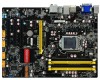
High Definition Audio - 2/4/5.1/7.1-channel - Support for S/PDIF Out - Support Jack-Sensing function Support hot plug Support up to 14 x USB 2.0 ports (6 rear panel ports, 4 onboard USB headers ...
High Definition Audio - 2/4/5.1/7.1-channel - Support for S/PDIF Out - Support Jack-Sensing function Support hot plug Support up to 14 x USB 2.0 ports (6 rear panel ports, 4 onboard USB headers ...

Manual
Page 12
... using it. Use this port for USB devices such as monitor or LCD display4. The USB port supports the USB 3.0/2.0/1.1 specification. Audio Ports For the definition of each audio port, please refer to connect a PS/2 keyboard. 2. 1 1-3 Back Panel Connectors PS/2 Keyboard Port VGA Port 1 3 LAN Port 2 9 Line Out Line In Rear...
... using it. Use this port for USB devices such as monitor or LCD display4. The USB port supports the USB 3.0/2.0/1.1 specification. Audio Ports For the definition of each audio port, please refer to connect a PS/2 keyboard. 2. 1 1-3 Back Panel Connectors PS/2 Keyboard Port VGA Port 1 3 LAN Port 2 9 Line Out Line In Rear...

Manual
Page 21
... power supply. 24-pin ATX Power Connector : PWR1 PWR1 is secure. If you need to align the ATX power connector according to the picture. Pin # Definition Pin # Definition 1 3.3V 13 3.3V 2 3.3V 14 -12V 3 GND 15 GND 4 +5V 16 PS_ON(Soft On/Off) 5 GND 17 GND 6 +5V 18 GND 7 ... Power Connectors This motherboard uses an ATX power supply. In order not to the CPU. +12V 51 GND 84 PWR2 Pin # 1 2 3 4 Definition GND GND GND GND Pin # 5 6 7 8 Definition +12V +12V +12V +12V 14 14 Make sure that the power supply cable and pins are using a 24-pin power supply.
... power supply. 24-pin ATX Power Connector : PWR1 PWR1 is secure. If you need to align the ATX power connector according to the picture. Pin # Definition Pin # Definition 1 3.3V 13 3.3V 2 3.3V 14 -12V 3 GND 15 GND 4 +5V 16 PS_ON(Soft On/Off) 5 GND 17 GND 6 +5V 18 GND 7 ... Power Connectors This motherboard uses an ATX power supply. In order not to the CPU. +12V 51 GND 84 PWR2 Pin # 1 2 3 4 Definition GND GND GND GND Pin # 5 6 7 8 Definition +12V +12V +12V +12V 14 14 Make sure that the power supply cable and pins are using a 24-pin power supply.

Manual
Page 25
... motherboard uses CMOS RAM to short them. Turn off the computer, unplug the power cord from pins 2-3, put it . Plug in next chapter. Jumper 1 Diagram 1 1 Definition 1-2 2-3 Description Set Pin 1 and Pin 2 closed Set Pin 2 and Pin 3 closed . 4. The steps to it onto pins 1-2 to store the basic hardware information (such as...
... motherboard uses CMOS RAM to short them. Turn off the computer, unplug the power cord from pins 2-3, put it . Plug in next chapter. Jumper 1 Diagram 1 1 Definition 1-2 2-3 Description Set Pin 1 and Pin 2 closed Set Pin 2 and Pin 3 closed . 4. The steps to it onto pins 1-2 to store the basic hardware information (such as...