
English manual
Page 1
... physical injury exists. More information: If you want more detailed information about our products, please visit Foxconn's website: http://www.foxconnchannel.com WEEE: The use motherboard better. For more information about recycling of this manual may damage hardware or cause data loss, and... at any time, Foxconn does not obligate itself to inform the user of these changes. Statement: This manual is disposed of correctly, you will help you to use of the symbol indicates that can help prevent potential negative consequences for X38A motherboard. Attention: indicates that...
... physical injury exists. More information: If you want more detailed information about our products, please visit Foxconn's website: http://www.foxconnchannel.com WEEE: The use motherboard better. For more information about recycling of this manual may damage hardware or cause data loss, and... at any time, Foxconn does not obligate itself to inform the user of these changes. Statement: This manual is disposed of correctly, you will help you to use of the symbol indicates that can help prevent potential negative consequences for X38A motherboard. Attention: indicates that...

English manual
Page 2
Declaration of information technology equipment Electromagnetic compatibility (EMC) Part 3: Limits Section 2: Limits for harmonic current emissions (equipment input current declares that the product Motherboard X38A is in conformity with (reference to the specification under which conformity is declared in accordance with 89/336 EEC-EMC Directive) þ EN 55022: 1998/...
Declaration of information technology equipment Electromagnetic compatibility (EMC) Part 3: Limits Section 2: Limits for harmonic current emissions (equipment input current declares that the product Motherboard X38A is in conformity with (reference to the specification under which conformity is declared in accordance with 89/336 EEC-EMC Directive) þ EN 55022: 1998/...

English manual
Page 3
...: Manufacturer: Address: FCC Class B Subassembly Motherboard HON HAI PRECISION INDUSTRY COMPANY LTD 66 , CHUNG SHAN RD., TU-CHENG INDUSTRIAL DISTRICT, TAIPEI HSIEN, TAIWAN, R.O.C. Fullerton, CA 92835 714-738-8868 714-738-8838 Equipment Classification: Type of conformity Trade Name: Model Name: Responsible Party: Address: Telephone: Facsimile: FOXCONN X38A PCE Industry Inc. 458 E. Lambert...
...: Manufacturer: Address: FCC Class B Subassembly Motherboard HON HAI PRECISION INDUSTRY COMPANY LTD 66 , CHUNG SHAN RD., TU-CHENG INDUSTRIAL DISTRICT, TAIPEI HSIEN, TAIWAN, R.O.C. Fullerton, CA 92835 714-738-8868 714-738-8838 Equipment Classification: Type of conformity Trade Name: Model Name: Responsible Party: Address: Telephone: Facsimile: FOXCONN X38A PCE Industry Inc. 458 E. Lambert...
English manual
Page 6
... refer to ensure full contact. 2. W e do not guarantee that your device. Attention: Please visit the Foxconn English website (http://www.foxconnchannel. Attention: W e cannot guarantee that the content of objects used in this motherboard. It is just for reference. com) to switch off before inserting or removing expansion cards or other peripherals, especially...
... refer to ensure full contact. 2. W e do not guarantee that your device. Attention: Please visit the Foxconn English website (http://www.foxconnchannel. Attention: W e cannot guarantee that the content of objects used in this motherboard. It is just for reference. com) to switch off before inserting or removing expansion cards or other peripherals, especially...
English manual
Page 7
...motherboards combine high-performance computing, wider options for multimedia and entertainment applications. The Digital Life series of products allow you to a world of connectivity options which enable easy access to do more flexibility from your PC for accessing and managing other devices, and technologies which enable more with your PC. 1 Chapter X38A... is the first product in a new series called Digital Life. Foxconn Digital Life products are engineered to maximize the computing power at your ...
...motherboards combine high-performance computing, wider options for multimedia and entertainment applications. The Digital Life series of products allow you to a world of connectivity options which enable easy access to do more flexibility from your PC for accessing and managing other devices, and technologies which enable more with your PC. 1 Chapter X38A... is the first product in a new series called Digital Life. Foxconn Digital Life products are engineered to maximize the computing power at your ...

English manual
Page 8
Chapter 1 Product Introduction Package List: Check your motherboard package for the following items: Motherboard I/O modules Cables Accessory Application CD Documentation Foxconn X38A motherboard 1 X USB 2.0 x 2 ports and 1 x 1394a module 6 X SATA Power and SATA Signal cables 1 X Ultra DMA 133/100/66 and Floppy Disk Drive cable I/O Shield 1 X Foxconn Optional Fan Foxconn motherboard support CD User Manual Easy Guide Note: If any of the above item is damaged or missing, please contact your retailer. 2
Chapter 1 Product Introduction Package List: Check your motherboard package for the following items: Motherboard I/O modules Cables Accessory Application CD Documentation Foxconn X38A motherboard 1 X USB 2.0 x 2 ports and 1 x 1394a module 6 X SATA Power and SATA Signal cables 1 X Ultra DMA 133/100/66 and Floppy Disk Drive cable I/O Shield 1 X Foxconn Optional Fan Foxconn motherboard support CD User Manual Easy Guide Note: If any of the above item is damaged or missing, please contact your retailer. 2

English manual
Page 13
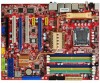
Layout Chapter 1 Product Introduction Note: The above motherboard layout is provided for reference only, please refer to the physical motherboard. 7
Layout Chapter 1 Product Introduction Note: The above motherboard layout is provided for reference only, please refer to the physical motherboard. 7

English manual
Page 14
Chapter 1 Product Introduction Rear I/O Ports This motherboard provides the ports as below: Line in, Line out, Microphone, Rear, Center/Bass and Side Jacks Port 2-channel Blue Line_in Green Line_out Pink Microphone Orange - ...
Chapter 1 Product Introduction Rear I/O Ports This motherboard provides the ports as below: Line in, Line out, Microphone, Rear, Center/Bass and Side Jacks Port 2-channel Blue Line_in Green Line_out Pink Microphone Orange - ...

English manual
Page 15
This chapter includes the following information: v CPU v Memory v Expansion Slots v Connectors v Jumpers v Onboard Buttons v Onboard LED Debug 9 Please refer to the motherboard layout prior to any installation and read the contents in this chapter carefully. Chapter 1 Product Introduction 2 Chapter This chapter introduces the hardware installation process, including the installation of these modules. Caution should be exercised during the installation of the CPU, memory, power supply, slots, and pin headers, an d the mounting o f jumpers.
This chapter includes the following information: v CPU v Memory v Expansion Slots v Connectors v Jumpers v Onboard Buttons v Onboard LED Debug 9 Please refer to the motherboard layout prior to any installation and read the contents in this chapter carefully. Chapter 1 Product Introduction 2 Chapter This chapter introduces the hardware installation process, including the installation of these modules. Caution should be exercised during the installation of the CPU, memory, power supply, slots, and pin headers, an d the mounting o f jumpers.

English manual
Page 16
...a CPU. Push down and away from socket to hold the hook of CPU Below is the CPU socket illustration. Chapter 2 Installation Instructions CPU This motherboard supports Intel® CoreTM 2 Quad, CoreTM 2 Extreme, CoreTM 2 Duo, Pentium® Dual-Core E2xxx processors in an LGA775 package with your ...Load lever Load plate Protective cover CPU Socket 775 1. Open the load plate with thumb. For the detailed CPU support list on this motherboard, please visit the website: http://www.foxconnchannel.com Installation of the load lever and pull the lever down the rear tab with Front Side...
...a CPU. Push down and away from socket to hold the hook of CPU Below is the CPU socket illustration. Chapter 2 Installation Instructions CPU This motherboard supports Intel® CoreTM 2 Quad, CoreTM 2 Extreme, CoreTM 2 Duo, Pentium® Dual-Core E2xxx processors in an LGA775 package with your ...Load lever Load plate Protective cover CPU Socket 775 1. Open the load plate with thumb. For the detailed CPU support list on this motherboard, please visit the website: http://www.foxconnchannel.com Installation of the load lever and pull the lever down the rear tab with Front Side...

English manual
Page 18
... the memory module can be fixed in damage to ensure normal operation. There is one memory bank to the motherboard and your system. 128-Pin 112-Pin Chapter 2 Installation Instructions Memory This motherboard includes four 240-pin slots with 1.8V for DDR2 and two 240pin slots with 1.5V for DDR3. You must... DDR3 DIMM slots: 240-pin DDR2 DIMM Slots 240-pin DDR3 DIMM Slots Warning: Do not install DDR2 and DDR3 memory modules simultaneously on this motherboard, doing so may result in one direction only. 12 96-Pin 144-Pin Installation a DIMM 1.
... the memory module can be fixed in damage to ensure normal operation. There is one memory bank to the motherboard and your system. 128-Pin 112-Pin Chapter 2 Installation Instructions Memory This motherboard includes four 240-pin slots with 1.8V for DDR2 and two 240pin slots with 1.5V for DDR3. You must... DDR3 DIMM slots: 240-pin DDR2 DIMM Slots 240-pin DDR3 DIMM Slots Warning: Do not install DDR2 and DDR3 memory modules simultaneously on this motherboard, doing so may result in one direction only. 12 96-Pin 144-Pin Installation a DIMM 1.

English manual
Page 19
... less bandwidth-intensive cards, such as a LAN card, USB card, SCSI card and other system peripherals, especially the memory modules, otherwise the motherboard or the system might be installed in the two PCI slots. Two PCI Express x16 slots offering 8GB/s (16GB/s concurrent) of bandwidth and...damaged. Removing a DIMM 1. Warning: Be sure to the DIMM slot, and insert the module vertically into the DIMM slot. 3. Expansion Slots This motherboard includes two 32-bit master PCI slots, two PCI Express x1 slots and three PCI Express x16 slots. ing the module clips outward. 2. Chapter 2...
... less bandwidth-intensive cards, such as a LAN card, USB card, SCSI card and other system peripherals, especially the memory modules, otherwise the motherboard or the system might be installed in the two PCI slots. Two PCI Express x16 slots offering 8GB/s (16GB/s concurrent) of bandwidth and...damaged. Removing a DIMM 1. Warning: Be sure to the DIMM slot, and insert the module vertically into the DIMM slot. 3. Expansion Slots This motherboard includes two 32-bit master PCI slots, two PCI Express x1 slots and three PCI Express x16 slots. ing the module clips outward. 2. Chapter 2...

English manual
Page 21
... the ATX power connector according to the CPU. Make sure that the power supply cable and pins are properly aligned with the connector on the motherboard. Make sure that they have been installed properly prior to connecting the power supply. 24-pin ATX power connector: PWR1 PW R1 is secure. 8-...12V power supply connects to PWR2 and provides power to the following picture. 20-Pin Power 24-Pin Power 15 Chapter 2 Installation Instructions Connectors This motherboard includes connectors for power supply, FDD device, IDE device, Serial ATA devices, USB devices, IR module, and others.
... the ATX power connector according to the CPU. Make sure that the power supply cable and pins are properly aligned with the connector on the motherboard. Make sure that they have been installed properly prior to connecting the power supply. 24-pin ATX power connector: PWR1 PW R1 is secure. 8-...12V power supply connects to PWR2 and provides power to the following picture. 20-Pin Power 24-Pin Power 15 Chapter 2 Installation Instructions Connectors This motherboard includes connectors for power supply, FDD device, IDE device, Serial ATA devices, USB devices, IR module, and others.

English manual
Page 22
Connect a 4-pin power plug here 5 1 8 4 FDD Connector: FLOPPY This motherboard includes a standard Floppy connector, supporting [360KB, 51/4 in], [1.2MB, 51/4in], [720KB, 31/2 in], [1.44MB, 31/2 in], [2.88 MB, 31/2 in] FDDs. Attention: If you ...: We recommend you use 4-pin power supply, you need to align the ATX power connector according to the right picture. Front Panel Connector: FP1 This motherboard includes one connector for connecting the front panel switch and LED indicators. 1 + HD_LED - 2 + - PWR_LED RESET PWRSW NC 9 10 FPFP1! the system will restart when the...
Connect a 4-pin power plug here 5 1 8 4 FDD Connector: FLOPPY This motherboard includes a standard Floppy connector, supporting [360KB, 51/4 in], [1.2MB, 51/4in], [720KB, 31/2 in], [1.44MB, 31/2 in], [2.88 MB, 31/2 in] FDDs. Attention: If you ...: We recommend you use 4-pin power supply, you need to align the ATX power connector according to the right picture. Front Panel Connector: FP1 This motherboard includes one connector for connecting the front panel switch and LED indicators. 1 + HD_LED - 2 + - PWR_LED RESET PWRSW NC 9 10 FPFP1! the system will restart when the...

English manual
Page 23
... LED is off rather than using the power supply button. Front Audio supports retasking function. The current Serial ATA II interface allows up to the motherboard. Power Switch Connector (PWRSW) Attach the connector to the power LED on the front panel of the case. Chapter 2 Installation Instructions Power LED Connector (PW...
... LED is off rather than using the power supply button. Front Audio supports retasking function. The current Serial ATA II interface allows up to the motherboard. Power Switch Connector (PWRSW) Attach the connector to the power LED on the front panel of the case. Chapter 2 Installation Instructions Power LED Connector (PW...

English manual
Page 24
... the serial port module cable to the connector, then install the module to a slot opening at the back of motherboard also have two 10-pin headers onboard, which may be connected to either the front (provided that the front panel of each USB pin headers ...
... the serial port module cable to the connector, then install the module to a slot opening at the back of motherboard also have two 10-pin headers onboard, which may be connected to either the front (provided that the front panel of each USB pin headers ...

English manual
Page 25
Connect the module cable to this motherboard. TPB + GND TPA - The fan speed can be automatically turned off after the system enters S3, S4 and S5 mode. 1 GND POWER SENSE CONTROL CPU_FAN 1 ...
Connect the module cable to this motherboard. TPB + GND TPA - The fan speed can be automatically turned off after the system enters S3, S4 and S5 mode. 1 GND POWER SENSE CONTROL CPU_FAN 1 ...

English manual
Page 27
... cap back to load defaults. 1 Clear 1 Normal (default) Clear CMOS Jumper CLR_ CMOS 21 and in CMOS. Plug the power cord and turn on the motherboard, pin 1 can be identified by the bold silkscreen next to clear the data in this manual, pin 1 is simply labeled as system password, data, time...
... cap back to load defaults. 1 Clear 1 Normal (default) Clear CMOS Jumper CLR_ CMOS 21 and in CMOS. Plug the power cord and turn on the motherboard, pin 1 can be identified by the bold silkscreen next to clear the data in this manual, pin 1 is simply labeled as system password, data, time...
English manual
Page 28
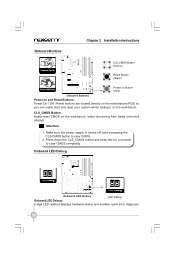
... (Yellow) Reset Button (Black) Power on Button (Red) Onboard Buttons Power on and Reset Buttons: Power On / Off / Reset buttons are located directly on the motherboard PCB, so you can easily start and reset your system whilst testing it on the workbench, when recovering from failed overclock attempt. Attention: 1. Make sure...
... (Yellow) Reset Button (Black) Power on Button (Red) Onboard Buttons Power on and Reset Buttons: Power On / Off / Reset buttons are located directly on the motherboard PCB, so you can easily start and reset your system whilst testing it on the workbench, when recovering from failed overclock attempt. Attention: 1. Make sure...
English manual
Page 58
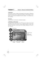
... determine the current performance level of the system. You can adjust manually or select "Auto Overclock". Go to CPU page Close this button to visit Foxconn motherboard website. 2. Chapter 4 Directions for Bundled Software Configuration This function is used to configure the parameters for the program. It determines which will be shown in...
... determine the current performance level of the system. You can adjust manually or select "Auto Overclock". Go to CPU page Close this button to visit Foxconn motherboard website. 2. Chapter 4 Directions for Bundled Software Configuration This function is used to configure the parameters for the program. It determines which will be shown in...


