
User Manual
Page 9
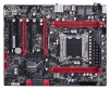
...is installed devices) - PCI-E2_16X support 8X bandwidth - 1-1 Product Specifications 1 CPU Chipset Memory Expansion Slots Multi-GPU Support Storage LAN Audio USB Internal Connectors Support LGA2011 socket for S/PDIF Out -Support Jack-Sensing function Support hot plug Support up to 10 x USB 2.0 ports (6 rear panel ports, 2 onboard USB headers supporting 4 extra ports) Support USB 2.0 protocol up to 480Mb/s Support up to 4 x USB 3.0 ports (2 rear panel ports, 1 onboard USB header supporting 2 extra ports) Support USB 3.0 protocol up to 5Gb/s 1 x 24-Pin ATX power connector 1 x 8-pin ATX 12V...
...is installed devices) - PCI-E2_16X support 8X bandwidth - 1-1 Product Specifications 1 CPU Chipset Memory Expansion Slots Multi-GPU Support Storage LAN Audio USB Internal Connectors Support LGA2011 socket for S/PDIF Out -Support Jack-Sensing function Support hot plug Support up to 10 x USB 2.0 ports (6 rear panel ports, 2 onboard USB headers supporting 4 extra ports) Support USB 2.0 protocol up to 480Mb/s Support up to 4 x USB 3.0 ports (2 rear panel ports, 1 onboard USB header supporting 2 extra ports) Support USB 3.0 protocol up to 5Gb/s 1 x 24-Pin ATX power connector 1 x 8-pin ATX 12V...

User Manual
Page 10
...pin) 1 x Front pannel header 1 x Front Audio header 1 x CD-IN header 1 x Speaker header 4 x SATA 3.0 connectors 4 x SATA 2.0 connectors 2 x USB 2.0 headers 1 x USB 3.0 header 2 x SPDIF OUT headers OC button Power On/Off button Reset button Debug LED 1 x PS/2 Keyboard port 6 x USB 2.0 ports 1 x Clear CMOS button 1 x Optical S/PDIF out port 1 x Coaxial S/PDIF out port 2 x LAN ports 2 x USB 3.0 ports 2 x eSATA ports 6 ports audio jacks System voltage detection CPU/System temperature detection CPU/System fan speed detection CPU Overheating warning CPU/System fan speed control Support PCI Express...
...pin) 1 x Front pannel header 1 x Front Audio header 1 x CD-IN header 1 x Speaker header 4 x SATA 3.0 connectors 4 x SATA 2.0 connectors 2 x USB 2.0 headers 1 x USB 3.0 header 2 x SPDIF OUT headers OC button Power On/Off button Reset button Debug LED 1 x PS/2 Keyboard port 6 x USB 2.0 ports 1 x Clear CMOS button 1 x Optical S/PDIF out port 1 x Coaxial S/PDIF out port 2 x LAN ports 2 x USB 3.0 ports 2 x eSATA ports 6 ports audio jacks System voltage detection CPU/System temperature detection CPU/System fan speed detection CPU Overheating warning CPU/System fan speed control Support PCI Express...

User Manual
Page 14
... CPU and CPU Cooler ■ Install the Memory ■ Install an Expansion Card ■ Install other Internal Connectors ■ Jumpers ■ OnBoard Button ■ OnBoard Debug LED Please visit the following website for more supporting information about your motherboard. This chapter introduces the hardware installation process, including the installation of the CPU, memory, power supply, slots, pin headers and the mounting of these modules. Caution should be exercised during the installation of jumpers. Please refer to the motherboard layout...
... CPU and CPU Cooler ■ Install the Memory ■ Install an Expansion Card ■ Install other Internal Connectors ■ Jumpers ■ OnBoard Button ■ OnBoard Debug LED Please visit the following website for more supporting information about your motherboard. This chapter introduces the hardware installation process, including the installation of the CPU, memory, power supply, slots, pin headers and the mounting of these modules. Caution should be exercised during the installation of jumpers. Please refer to the motherboard layout...
User Manual
Page 20
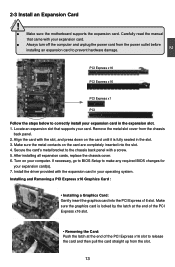
If necessary, go to BIOS Setup to make any required BIOS changes for your computer. CAUTION 2 2-3 Install an Expansion Card ! ■ Make sure the motherboard supports the expansion card. Carefully read the manual that supports your expansion card. ■ Always turn off the computer and unplug the power cord from the chassis back panel. 2. Installing and Removing a PCI Express x16 Graphics Card : • Installing a Graphics Card: Gently insert the graphics card into the slot. 4. Secure the card's metal bracket to...
If necessary, go to BIOS Setup to make any required BIOS changes for your computer. CAUTION 2 2-3 Install an Expansion Card ! ■ Make sure the motherboard supports the expansion card. Carefully read the manual that supports your expansion card. ■ Always turn off the computer and unplug the power cord from the chassis back panel. 2. Installing and Removing a PCI Express x16 Graphics Card : • Installing a Graphics Card: Gently insert the graphics card into the slot. 4. Secure the card's metal bracket to...

User Manual
Page 23
... S3/S4 sleep state or power off . SPDIF_OUT 1 GND 2 SPDIF_OUT3 16 16 Reset Switch (RESET-SW) Attach the connector to the power button on the front panel of the chassis. It indicates the active status of the chassis. When the system gets into sleep mode (S1) , the LED is on. sign. Speaker Connector : SPEAKER The speaker connector is directional with +/- Hard Disk LED Connector (HDD-LED) Connect to connect speaker of the hard disks. This 2-pin connector is used to the chassis front panel IDE indicator LED.
... S3/S4 sleep state or power off . SPDIF_OUT 1 GND 2 SPDIF_OUT3 16 16 Reset Switch (RESET-SW) Attach the connector to the power button on the front panel of the chassis. It indicates the active status of the chassis. When the system gets into sleep mode (S1) , the LED is on. sign. Speaker Connector : SPEAKER The speaker connector is directional with +/- Hard Disk LED Connector (HDD-LED) Connect to connect speaker of the hard disks. This 2-pin connector is used to the chassis front panel IDE indicator LED.
User Manual
Page 25
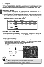
...;n�. 18 18 Jumper 1 1 Diagram 1 1 1 1 Definition Closed Open 1-2 2-3 Description Set Pin 1 and Pin 2 closed Set Pin 1 and Pin 2 Open Set Pin 1 and Pin 2 closed Set Pin 2 and Pin 3 closed Clear CMOS Jumper: CLR_CMOS The motherboard uses CMOS RAM to clear CMOS data are : 1. Turn off the computer, unplug the power cord from the power outlet. 2. Put a metal object(such as a screwdriver) onto pins 1-2 to configure new system as BIOS data, date, time information, hardware password...etc.). Go to BIOS Setup to short them.
...;n�. 18 18 Jumper 1 1 Diagram 1 1 1 1 Definition Closed Open 1-2 2-3 Description Set Pin 1 and Pin 2 closed Set Pin 1 and Pin 2 Open Set Pin 1 and Pin 2 closed Set Pin 2 and Pin 3 closed Clear CMOS Jumper: CLR_CMOS The motherboard uses CMOS RAM to clear CMOS data are : 1. Turn off the computer, unplug the power cord from the power outlet. 2. Put a metal object(such as a screwdriver) onto pins 1-2 to configure new system as BIOS data, date, time information, hardware password...etc.). Go to BIOS Setup to short them.

User Manual
Page 26
... power on . ■ Only suggest to use another work . 19 19 CAUTION SPI 2 Definition 1-2(default) 2-3 Description Set Pin 1 and Pin 2 closed Set Pin 2 and Pin 3 closed Function Select SPI1 (BIOS ROM 1) Select SPI2 (BIOS ROM 2) ! The effect is identical to boot from. Normal 1 2 (Default) 3 1 VBAT_DISCHARGE 2 3 VBAT_DISCHARGE ! ■ Disconnect the power cable before adjusting the jumper settings. ■ Do not discharge the battery while the system is turned on . CAUTION Discharge Battery Jumper: VBAT_DISCHARGE Resetting the CMOS...
... power on . ■ Only suggest to use another work . 19 19 CAUTION SPI 2 Definition 1-2(default) 2-3 Description Set Pin 1 and Pin 2 closed Set Pin 2 and Pin 3 closed Function Select SPI1 (BIOS ROM 1) Select SPI2 (BIOS ROM 2) ! The effect is identical to boot from. Normal 1 2 (Default) 3 1 VBAT_DISCHARGE 2 3 VBAT_DISCHARGE ! ■ Disconnect the power cable before adjusting the jumper settings. ■ Do not discharge the battery while the system is turned on . CAUTION Discharge Battery Jumper: VBAT_DISCHARGE Resetting the CMOS...
User Manual
Page 29
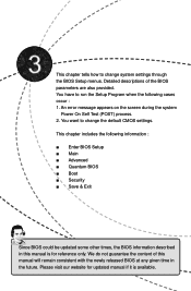
... this manual is for updated manual if it is available. You want to change system settings through the BIOS Setup menus. We do not guarantee the content of the BIOS parameters are also provided. An error message appears on the screen during the system Power On Self Test (POST) process. 2. This chapter tells how to change the default CMOS settings. This chapter includes the following cases occur...
... this manual is for updated manual if it is available. You want to change system settings through the BIOS Setup menus. We do not guarantee the content of the BIOS parameters are also provided. An error message appears on the screen during the system Power On Self Test (POST) process. 2. This chapter tells how to change the default CMOS settings. This chapter includes the following cases occur...

User Manual
Page 33
...ESC: Exit Version 2.14.1219. 3 Advanced Aptio Setup Utility - Legacy OpROM Support ► Launch PXE OpROM This item is used to enable or disable boot option for legacy network devices. ► Launch Storage OpROM This item is used to enable or disable boot option for legacy mass storage devices with option ROM. ► 80h Debug Code Send to The legacy I/O 80h debug port message will send to LPC bus or PCI bus as your selection. ► Onboard Device Configuration/Chipset Configuration/ACPI Settings/SATA Configuration/USB Configuration/Hardware Monitor Press [Enter] to go...
...ESC: Exit Version 2.14.1219. 3 Advanced Aptio Setup Utility - Legacy OpROM Support ► Launch PXE OpROM This item is used to enable or disable boot option for legacy network devices. ► Launch Storage OpROM This item is used to enable or disable boot option for legacy mass storage devices with option ROM. ► 80h Debug Code Send to The legacy I/O 80h debug port message will send to LPC bus or PCI bus as your selection. ► Onboard Device Configuration/Chipset Configuration/ACPI Settings/SATA Configuration/USB Configuration/Hardware Monitor Press [Enter] to go...

User Manual
Page 34
... Azalia HD Audio Onboard ESATA Controller NEC USB 3.0 Controller 1 NEC USB 3.0 Controller 2 Onboard SATA 3.0 Controller Onboard LAN Controller Intel Gigabit LAN Controller Realtek Gigabit LAN Controller [Enabled] [Enabled] [Enabled] [Enabled] [Enabled] [Enabled] [Enabled] [Enabled] Enabled/Disabled Boot Option for legacy Network Devices. → ← : Select Screen ↑ ↓ : Select Item Enter: Select +/-: Change Opt. F1: General Help F2: Previous Values F3: Optimized Defaults F4: Save & Exit ESC: Exit Version 2.14.1219. 3 Onboard Device Configuration Aptio Setup Utility...
... Azalia HD Audio Onboard ESATA Controller NEC USB 3.0 Controller 1 NEC USB 3.0 Controller 2 Onboard SATA 3.0 Controller Onboard LAN Controller Intel Gigabit LAN Controller Realtek Gigabit LAN Controller [Enabled] [Enabled] [Enabled] [Enabled] [Enabled] [Enabled] [Enabled] [Enabled] Enabled/Disabled Boot Option for legacy Network Devices. → ← : Select Screen ↑ ↓ : Select Item Enter: Select +/-: Change Opt. F1: General Help F2: Previous Values F3: Optimized Defaults F4: Save & Exit ESC: Exit Version 2.14.1219. 3 Onboard Device Configuration Aptio Setup Utility...

User Manual
Page 36
... LAN from S5 Wake on USB Device Wake on PCI device Wake on AC Power Loss This item is used to enable or disable the USB standby power. When you select "S1 (POS)" mode, the power is always on and computer can be saved in memory, and the computer can quickly return to RAM)] [Disabled] [Disabled] [Enabled] [Enabled] [Power Off] [Enabled] [Enabled] [Enabled] [Enabled] [Enabled] [Enabled] [Enabled] [Enabled] [Enabled] [Disabled] → ← : Select Screen ↑ ↓ : Select Item Enter: Select +/-: Change Opt. ACPI Configuration Aptio Setup Utility - When you select "Auto...
... LAN from S5 Wake on USB Device Wake on PCI device Wake on AC Power Loss This item is used to enable or disable the USB standby power. When you select "S1 (POS)" mode, the power is always on and computer can be saved in memory, and the computer can quickly return to RAM)] [Disabled] [Disabled] [Enabled] [Enabled] [Power Off] [Enabled] [Enabled] [Enabled] [Enabled] [Enabled] [Enabled] [Enabled] [Enabled] [Enabled] [Disabled] → ← : Select Screen ↑ ↓ : Select Item Enter: Select +/-: Change Opt. ACPI Configuration Aptio Setup Utility - When you select "Auto...

User Manual
Page 37
...-up SATA Port 2 Not Present Port Hot Plug External SATA Port Staggered Spin-up . The Advanced Host Controller Interface (AHCI) specification describes the reg- 30 SATA Configuration Aptio Setup Utility - Setting options: [Disabled]; [IDE Mode]; [AHCI Mode]; [RAID Mode]. [IDE Mode] - C opyright (C) 2011 American Megatrends, Inc. Disabling this function will reducing system power consumption when computer go into standby mode or power off state. ► Wake on PS/2 KB from S1 and S3 This item is used to enable or disable PS2 key board wake...
...-up SATA Port 2 Not Present Port Hot Plug External SATA Port Staggered Spin-up . The Advanced Host Controller Interface (AHCI) specification describes the reg- 30 SATA Configuration Aptio Setup Utility - Setting options: [Disabled]; [IDE Mode]; [AHCI Mode]; [RAID Mode]. [IDE Mode] - C opyright (C) 2011 American Megatrends, Inc. Disabling this function will reducing system power consumption when computer go into standby mode or power off state. ► Wake on PS/2 KB from S1 and S3 This item is used to enable or disable PS2 key board wake...

User Manual
Page 38
... is loaded by platform BIOS prior to [IDE Mode]) Serial-ATA Controller 1 are the SATA ports 5,6 of the SATA ports. This item allows you can select AHCI to the system. This item is used to enable or disable hot plug function for SATA hard disks when in RAID/AHCI mode. ► External SATA Port (Appears when "SATA Mode" is set to [AHCI Mode]) This item is used to process. Setting values are labeled with AHCI support in balancing power spikes. When enabled, the SATA controller will use...
... is loaded by platform BIOS prior to [IDE Mode]) Serial-ATA Controller 1 are the SATA ports 5,6 of the SATA ports. This item allows you can select AHCI to the system. This item is used to enable or disable hot plug function for SATA hard disks when in RAID/AHCI mode. ► External SATA Port (Appears when "SATA Mode" is set to [AHCI Mode]) This item is used to process. Setting values are labeled with AHCI support in balancing power spikes. When enabled, the SATA controller will use...

User Manual
Page 39
...USB keyboard or mouse, set the maximum time the device will disable the legacy support if no USB devices are connected. ► Legacy USB 3.0 Support This item is used to set to enabled. [Enabled]: This option will enable the legacy USB support. [Disabled]: This option will keep USB devices available only for EFI applications. [Auto]: This option will take before it can report itself to enable the support for OSes without EHCI hand-off support. Advanced USB Configuration All USB Devices EHCI Controller 1 EHCI Controller 2 [Enabled] [Enabled] [Enabled] Enabled/Disabled All USB...
...USB keyboard or mouse, set the maximum time the device will disable the legacy support if no USB devices are connected. ► Legacy USB 3.0 Support This item is used to set to enabled. [Enabled]: This option will enable the legacy USB support. [Disabled]: This option will keep USB devices available only for EFI applications. [Auto]: This option will take before it can report itself to enable the support for OSes without EHCI hand-off support. Advanced USB Configuration All USB Devices EHCI Controller 1 EHCI Controller 2 [Enabled] [Enabled] [Enabled] Enabled/Disabled All USB...

User Manual
Page 41
... CPU Core Clock and the FSB Frequency. Quantum BIOS Aptio Setup Utility - Main Advanced Quantum BIOS Boot Security Save & Exit Quantum BIOS Configuration Host Clock Multiplier CPU Bclock (FSB) Set the host clock multiplier [1 s e t t i n g 100.0 MHz] ▶ CPU Configuration ▶ Memory Configuration ▶ Voltage Configuration 3 → ← : Select Screen ↑ ↓ : Select Item Enter: Select +/-: Change Opt. The default value is used to set the host clock multiplier. ► CPU Bclock(FSB) This item is [100 MHz]. ► CPU Configuration / Memory...
... CPU Core Clock and the FSB Frequency. Quantum BIOS Aptio Setup Utility - Main Advanced Quantum BIOS Boot Security Save & Exit Quantum BIOS Configuration Host Clock Multiplier CPU Bclock (FSB) Set the host clock multiplier [1 s e t t i n g 100.0 MHz] ▶ CPU Configuration ▶ Memory Configuration ▶ Voltage Configuration 3 → ← : Select Screen ↑ ↓ : Select Item Enter: Select +/-: Change Opt. The default value is used to set the host clock multiplier. ► CPU Bclock(FSB) This item is [100 MHz]. ► CPU Configuration / Memory...
User Manual
Page 42
... supporting this limit is for factory long duration power limit. It should be met, including CPU, chipset, motherboard, BIOS and operation system. Execute Disable Bit allows the processor to set the power limit 2 value. Default value is used to enable or disable the feature. This option is used to set IA Core current max value for 1/2/3/4/5/6 core active. 0 means using the factory-configured value. ► Limit CPUID Maximum This item is used to insert code in memory...
... supporting this limit is for factory long duration power limit. It should be met, including CPU, chipset, motherboard, BIOS and operation system. Execute Disable Bit allows the processor to set the power limit 2 value. Default value is used to enable or disable the feature. This option is used to set IA Core current max value for 1/2/3/4/5/6 core active. 0 means using the factory-configured value. ► Limit CPUID Maximum This item is used to insert code in memory...
User Manual
Page 66
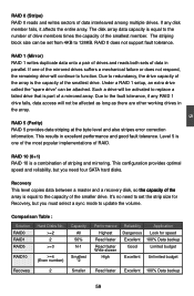
RAID 0 does not support fault tolerance. RAID 1 (Mirror) RAID 1 writes duplicate data onto a pair of drives and reads both sets of data in the array. Such a drive will be set the strip size for speed Excellent 100% Data backup Good Limited budget Excellent Unlimited budget Read faster Excellent 100% Data backup 59 Due to replace a failed drive that is part of the smallest drive. RAID 10...
RAID 0 does not support fault tolerance. RAID 1 (Mirror) RAID 1 writes duplicate data onto a pair of drives and reads both sets of data in the array. Such a drive will be set the strip size for speed Excellent 100% Data backup Good Limited budget Excellent Unlimited budget Read faster Excellent 100% Data backup 59 Due to replace a failed drive that is part of the smallest drive. RAID 10...

User Manual
Page 70
... configuration items. 3. Delete RAID Volume 4. Enter the BIOS setup by pressing key during the POST(Power On Self Test). 2. Intel(R) Rapid Storage Technology enterprise - 5 5-2 BIOS Configuration 1. Exit [ DISK /VOLU ME INF ORMATION ] RAID Volume : None Defined. Use the arrow right/left keys to select the "Advanced" menu, then use the arrow up/down keys to select the "SATA Configuration" item and press to go to enter the main menu of Intel® Rapid Storage Technology enterprise Option ROM Utility...
... configuration items. 3. Delete RAID Volume 4. Enter the BIOS setup by pressing key during the POST(Power On Self Test). 2. Intel(R) Rapid Storage Technology enterprise - 5 5-2 BIOS Configuration 1. Exit [ DISK /VOLU ME INF ORMATION ] RAID Volume : None Defined. Use the arrow right/left keys to select the "Advanced" menu, then use the arrow up/down keys to select the "SATA Configuration" item and press to go to enter the main menu of Intel® Rapid Storage Technology enterprise Option ROM Utility...

User Manual
Page 99
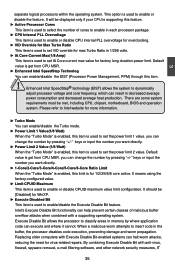
...UEFI Boot [Disabled] [Enabled] [On] [Disabled] Enables or disables Quiet Boot Option Set Boot Priority 1st Boot 2nd Boot 3rd Boot 4th Boot 5th Boot 6th Boot 7th Boot 8th Boot [CD/DVD] [Hard Disk] [USB Flash] [USB Floppy] [USB CD/DVD] [USB Hard Disk] [Network] [UEFI] → ← : Select Screen ↑ ↓ : Select Item Enter: Select +/-: Change Opt. Watch the screen carefully, when the following steps to either AHCI or RAID, you can install Windows XP directly. PC may need to install a third party SCSI or RAID driver. 92 When set the SATA Mode in BIOS to IDE...
...UEFI Boot [Disabled] [Enabled] [On] [Disabled] Enables or disables Quiet Boot Option Set Boot Priority 1st Boot 2nd Boot 3rd Boot 4th Boot 5th Boot 6th Boot 7th Boot 8th Boot [CD/DVD] [Hard Disk] [USB Flash] [USB Floppy] [USB CD/DVD] [USB Hard Disk] [Network] [UEFI] → ← : Select Screen ↑ ↓ : Select Item Enter: Select +/-: Change Opt. Watch the screen carefully, when the following steps to either AHCI or RAID, you can install Windows XP directly. PC may need to install a third party SCSI or RAID driver. 92 When set the SATA Mode in BIOS to IDE...
User Manual
Page 100
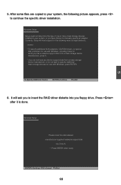
... the type of one or more mass storage devices installed in your system, the following mass storage device(s): * To specify additional SCSI adapters, CD-ROM drivers, or special disk controllers for use with Windows, press ENTER. Windows Setup Please insert the disk labeled manufacturer-supplied hardware support disk into you to continue the specific driver installation. Press after it is done. S=Specify Additional Device ENTER=Continue F3=Exit 6. 5 5. Currently, Setup will ask you floppy drive. It will load support...
... the type of one or more mass storage devices installed in your system, the following mass storage device(s): * To specify additional SCSI adapters, CD-ROM drivers, or special disk controllers for use with Windows, press ENTER. Windows Setup Please insert the disk labeled manufacturer-supplied hardware support disk into you to continue the specific driver installation. Press after it is done. S=Specify Additional Device ENTER=Continue F3=Exit 6. 5 5. Currently, Setup will ask you floppy drive. It will load support...


