English manual.
Page 1
... this product may be treated as household waste. More information: If you want more detailed information about our products, please visit Foxconn's website: http://www.foxconnchannel.com WEEE: The use motherboard better. Trademark: All trademarks are the property of their respective owners. For more information about recycling of this manual may not..., your household waste disposal service or the shop where you how to avoid such problems. Warning: means that can help prevent potential negative consequences for P35AP-S Series motherboard.
... this product may be treated as household waste. More information: If you want more detailed information about our products, please visit Foxconn's website: http://www.foxconnchannel.com WEEE: The use motherboard better. Trademark: All trademarks are the property of their respective owners. For more information about recycling of this manual may not..., your household waste disposal service or the shop where you how to avoid such problems. Warning: means that can help prevent potential negative consequences for P35AP-S Series motherboard.
English manual.
Page 2
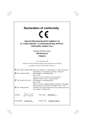
declares that the product Motherboard P35AP-S is in conformity with (reference to the specification under which conformity is declared in accordance with 89/336 EEC-EMC Directive) þ EN 55022: 1998/...
declares that the product Motherboard P35AP-S is in conformity with (reference to the specification under which conformity is declared in accordance with 89/336 EEC-EMC Directive) þ EN 55022: 1998/...

English manual.
Page 3
...: Manufacturer: Address: FCC Class B Subassembly Motherboard HON HAI PRECISION INDUSTRY COMPANY LTD 66 , CHUNG SHAN RD., TU-CHENG INDUSTRIAL DISTRICT, TAIPEI HSIEN, TAIWAN, R.O.C. Fullerton, CA 92835 714-738-8868 714-738-8838 Equipment Classification: Type of conformity Trade Name: Model Name: Responsible Party: Address: Telephone: Facsimile: FOXCONN P35AP-S PCE Industry Inc. 458 E. Supplementary...
...: Manufacturer: Address: FCC Class B Subassembly Motherboard HON HAI PRECISION INDUSTRY COMPANY LTD 66 , CHUNG SHAN RD., TU-CHENG INDUSTRIAL DISTRICT, TAIPEI HSIEN, TAIWAN, R.O.C. Fullerton, CA 92835 714-738-8868 714-738-8838 Equipment Classification: Type of conformity Trade Name: Model Name: Responsible Party: Address: Telephone: Facsimile: FOXCONN P35AP-S PCE Industry Inc. 458 E. Supplementary...
English manual.
Page 6
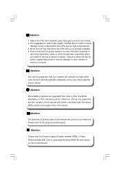
...to ensure full contact. 2. Failure to high temperatures. 3. W e do not guarantee that the DC power supply is suggested to the physical motherboard. Normal operation depends on the machine if the CPU fan is just for reference. Attach the CPU and heatsink using silica gel to download the... latest BIOS file and drivers for your device. Ensure that the content of your reference. Attention: Please visit the Foxconn global English website (http://www. Never turn on the over -clocked. Please refer to select high-quality, certified fans in the future....
...to ensure full contact. 2. Failure to high temperatures. 3. W e do not guarantee that the DC power supply is suggested to the physical motherboard. Normal operation depends on the machine if the CPU fan is just for reference. Attach the CPU and heatsink using silica gel to download the... latest BIOS file and drivers for your device. Ensure that the content of your reference. Attention: Please visit the Foxconn global English website (http://www. Never turn on the over -clocked. Please refer to select high-quality, certified fans in the future....
English manual.
Page 7
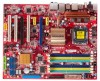
This chapter includes the following information: v Main Features v Layout v Rear I/O Ports 1 Chapter Thank you for users. This motherboard adopts the advanced Intel® P35 + ICH9R chipset, providing a computer platform with high integration, powerful compatibility and high performance-price ratio for buying Foxconn's P35AP-S Series motherboard. This series of motherboard is one of our new products, and offers superior performance, reliability and quality, at a reasonable price.
This chapter includes the following information: v Main Features v Layout v Rear I/O Ports 1 Chapter Thank you for users. This motherboard adopts the advanced Intel® P35 + ICH9R chipset, providing a computer platform with high integration, powerful compatibility and high performance-price ratio for buying Foxconn's P35AP-S Series motherboard. This series of motherboard is one of our new products, and offers superior performance, reliability and quality, at a reasonable price.
English manual.
Page 10
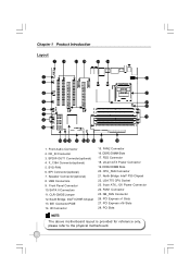
.... DDR2 DIMM Slots 20. CPU_FAN Connector 21. NB_FAN Connector 26. PCI Express x16 Slots 28. PCI Slots NOTE: The above motherboard layout is provided for reference only, please refer to the physical motherboard. 4 CD_IN Connector 3. Speaker Connector(optional) 8. LGA 775 CPU Socket 23. 8-pin ATX_12V Power Connector 24. SPDIF-OUT1 Connector(optional...
.... DDR2 DIMM Slots 20. CPU_FAN Connector 21. NB_FAN Connector 26. PCI Express x16 Slots 28. PCI Slots NOTE: The above motherboard layout is provided for reference only, please refer to the physical motherboard. 4 CD_IN Connector 3. Speaker Connector(optional) 8. LGA 775 CPU Socket 23. 8-pin ATX_12V Power Connector 24. SPDIF-OUT1 Connector(optional...
English manual.
Page 11
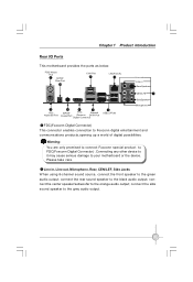
... I/O Ports This motherboard provides the ports as below: PS/2 Mouse Port 1 S/PDIF Fiber Port 10 1394 Port 9 LAN Port(-K) 8 Line-out Line-in , Line out, Microphone, Rear, CEN/LEF, Side Jacks W hen using 8-channel sound source, connect the front speaker to Foxconn digital entertainment and communications...audio output; connect the rear sound speaker to the grey audio output. 5 Warning: You are only promised to connect Foxconn special product to FDC(Foxconn Digital Connector) .Connecting any other device to it may cause serious damage to the orange audio output; connect the ...
... I/O Ports This motherboard provides the ports as below: PS/2 Mouse Port 1 S/PDIF Fiber Port 10 1394 Port 9 LAN Port(-K) 8 Line-out Line-in , Line out, Microphone, Rear, CEN/LEF, Side Jacks W hen using 8-channel sound source, connect the front speaker to Foxconn digital entertainment and communications...audio output; connect the rear sound speaker to the grey audio output. 5 Warning: You are only promised to connect Foxconn special product to FDC(Foxconn Digital Connector) .Connecting any other device to it may cause serious damage to the orange audio output; connect the ...

English manual.
Page 12
Chapter 1 Product Introduction 2 Chapter This chapter introduces the hardware installation process, including the installation of the CPU, memory, power supply, slots, pin headers, and the mounting of these modules. Caution should be exercised during the installation of jumpers. Please refer to the motherboard layout prior to any installation and read the contents in this chapter carefully. This chapter includes the following information: v CPU v Memory v Power Supply v Other Connectors v Expansion Slots v Jumpers 6
Chapter 1 Product Introduction 2 Chapter This chapter introduces the hardware installation process, including the installation of the CPU, memory, power supply, slots, pin headers, and the mounting of these modules. Caution should be exercised during the installation of jumpers. Please refer to the motherboard layout prior to any installation and read the contents in this chapter carefully. This chapter includes the following information: v CPU v Memory v Power Supply v Other Connectors v Expansion Slots v Jumpers 6
English manual.
Page 13
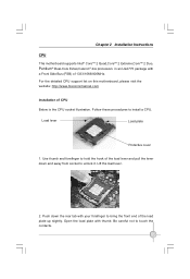
... to unlock it. Open the load plate with a Front Side Bus (FSB) of CPU Below is the CPU socket illustration. Chapter 2 Installation Instructions CPU This motherboard supports Intel® CoreTM 2 Quad,CoreTM 2 Extreme,CoreTM 2 Duo, Pentium® Dual-Core E2xxx,Celeron® 4xx processors in an LGA775 package with thumb. For...
... to unlock it. Open the load plate with a Front Side Bus (FSB) of CPU Below is the CPU socket illustration. Chapter 2 Installation Instructions CPU This motherboard supports Intel® CoreTM 2 Quad,CoreTM 2 Extreme,CoreTM 2 Duo, Pentium® Dual-Core E2xxx,Celeron® 4xx processors in an LGA775 package with thumb. For...
English manual.
Page 15
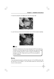
... completely. Please refer to the CPU. Therefore you should install the CPU cooling fan and make sure that it to ensure normal operation. 9 Memory This motherboard includes four 240-pin slots with 1.5V For DDR3 . Note : Excessive temperatures will severely damage the CPU and system. Chapter 2 Installation Instructions 5. Close the load...
... completely. Please refer to the CPU. Therefore you should install the CPU cooling fan and make sure that it to ensure normal operation. 9 Memory This motherboard includes four 240-pin slots with 1.5V For DDR3 . Note : Excessive temperatures will severely damage the CPU and system. Chapter 2 Installation Instructions 5. Close the load...
English manual.
Page 16
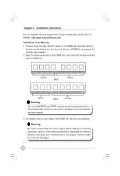
...damaged. 10 Unlock a DIMM slot by pressing the module clips outward. 2. Chapter 2 Installation Instructions For the detailed memory support list on this motherboard, please visit the website: http://www.foxconnchannel.com Installation of the Memory 1. Doing so may result in one direction only. Warning: Be ...sure to the motherboard and your motherboard or the system memory might be fixed in damage to unplug the AC power supply before adding or removing expansion cards or ...
...damaged. 10 Unlock a DIMM slot by pressing the module clips outward. 2. Chapter 2 Installation Instructions For the detailed memory support list on this motherboard, please visit the website: http://www.foxconnchannel.com Installation of the Memory 1. Doing so may result in one direction only. Warning: Be ...sure to the motherboard and your motherboard or the system memory might be fixed in damage to unplug the AC power supply before adding or removing expansion cards or ...
English manual.
Page 17
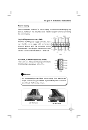
...power supply connector. If you want to the following picture. 20-Pin Power 24-Pin Power 11 Chapter 2 Installation Instructions Power Supply This motherboard uses an ATX power supply. Firmly plug the power supply cable into the connector and make sure that the power supply cable and pins are... properly aligned with the connector on the 13 24 motherboard. Attention: 5 12V 12V 12V 12V 8 PWR2 1 GND GND GND GND 4 W e recommend you need to align the ATX power connector according to use...
...power supply connector. If you want to the following picture. 20-Pin Power 24-Pin Power 11 Chapter 2 Installation Instructions Power Supply This motherboard uses an ATX power supply. Firmly plug the power supply cable into the connector and make sure that the power supply cable and pins are... properly aligned with the connector on the 13 24 motherboard. Attention: 5 12V 12V 12V 12V 8 PWR2 1 GND GND GND GND 4 W e recommend you need to align the ATX power connector according to use...
English manual.
Page 18
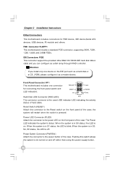
...(HDD-LED) FP1! W hen the system is in S0 status, the LED is blink; Chapter 2 Installation Instructions Other Connectors This motherboard includes connectors for connecting the front panel switch and LED indicators. Power Switch Connector (PWRSW) Attach the connector to the case's IDE ... a disk array through RAID controller. When the system is in S3, S4, S5 status, the LED is pressed. FDD Connector: FLOPPY This motherboard includes a standard FDD connector, supporting 360K, 720K, 1.2M, 1.44M, and 2.88M FDDs. IDE Connectors: PIDE This connector support the provided...
...(HDD-LED) FP1! W hen the system is in S0 status, the LED is blink; Chapter 2 Installation Instructions Other Connectors This motherboard includes connectors for connecting the front panel switch and LED indicators. Power Switch Connector (PWRSW) Attach the connector to the case's IDE ... a disk array through RAID controller. When the system is in S3, S4, S5 status, the LED is pressed. FDD Connector: FLOPPY This motherboard includes a standard FDD connector, supporting 360K, 720K, 1.2M, 1.44M, and 2.88M FDDs. IDE Connectors: PIDE This connector support the provided...
English manual.
Page 19
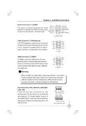
...correctly, otherwise the USB ports will be detected and viewed in "PC Health Status" section of the CMOS Setup. Incorrect connection could also damage the motherboard. D- make sure to the four USB ports on board which may connect to the front panel USB cable to the marker of the chassis. SENSE_SEND... enters S3, S4 and S5 mode. 1 GND +12V SENSE FAN1/2,NB-FAN GND SENSE 1 POWER CONTROL CPU_FAN,SYS_FAN 13 It provides two kinds of motherboards also have two 10-pin connectors on the rear panel,the series of audio output PORT2_R choices: the Front Audio, the Rear Audio. VCC VCC...
...correctly, otherwise the USB ports will be detected and viewed in "PC Health Status" section of the CMOS Setup. Incorrect connection could also damage the motherboard. D- make sure to the four USB ports on board which may connect to the front panel USB cable to the marker of the chassis. SENSE_SEND... enters S3, S4 and S5 mode. 1 GND +12V SENSE FAN1/2,NB-FAN GND SENSE 1 POWER CONTROL CPU_FAN,SYS_FAN 13 It provides two kinds of motherboards also have two 10-pin connectors on the rear panel,the series of audio output PORT2_R choices: the Front Audio, the Rear Audio. VCC VCC...
English manual.
Page 20
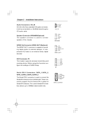
... ATA II Connectors: SATA_1,SATA_2, SATA_3,SATA_4,SATA_5,SATA_6 The Serial ATA II connector is used to connect the Serial ATA II device to the motherboard. CD_R GND 1 CD_L CD_IN SPKJ NC EMPTY 1 +5V SPEAKER 1 +5V EMPTY SPDIF_OUT GND SPDIF_OUT1 1 IR IRTX GND IRRX Empty +5V GND RX+RX- IrDA Connector...
... ATA II Connectors: SATA_1,SATA_2, SATA_3,SATA_4,SATA_5,SATA_6 The Serial ATA II connector is used to connect the Serial ATA II device to the motherboard. CD_R GND 1 CD_L CD_IN SPKJ NC EMPTY 1 +5V SPEAKER 1 +5V EMPTY SPDIF_OUT GND SPDIF_OUT1 1 IR IRTX GND IRRX Empty +5V GND RX+RX- IrDA Connector...
English manual.
Page 21
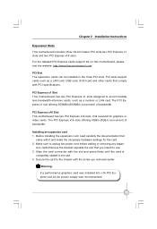
... to the chassis with it and make the necessary hardware settings for graphics or video cards. Chapter 2 Installation Instructions Expansion Slots This motherboard includes three 32-bit master PCI slots,two PCI Express x1 slots and two PCI Express x16 slots. For the detailed PCI Express cards... slot that reserved for the card. 2. The PCI Express x16 slots offering 4GB/s (8GB/s concurrent) of bandwidth. PCI Express x1 Slot This motherboard has two PCI Express x1 slots designed to accommodate less bandwidth-intensive cards, such as a LAN card, USB card, SCSI card and other cards...
... to the chassis with it and make the necessary hardware settings for graphics or video cards. Chapter 2 Installation Instructions Expansion Slots This motherboard includes three 32-bit master PCI slots,two PCI Express x1 slots and two PCI Express x16 slots. For the detailed PCI Express cards... slot that reserved for the card. 2. The PCI Express x16 slots offering 4GB/s (8GB/s concurrent) of bandwidth. PCI Express x1 Slot This motherboard has two PCI Express x1 slots designed to accommodate less bandwidth-intensive cards, such as a LAN card, USB card, SCSI card and other cards...
English manual.
Page 22
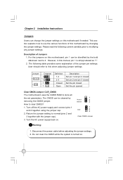
...supply and connect pins 1 and 2 together using the jumper cap. 2. The following content carefully prior to it. However, in this motherboard if needed. The CMOS can be identified by the bold silkscreen next to modifying any jumper settings. Please read the following table provides some... explanation of Jumpers 1. For the jumpers on this motherboard, pin 1 can change the jumper settings on this manual, pin 1 is turned on . Disconnect the power cable before adjusting the ...
...supply and connect pins 1 and 2 together using the jumper cap. 2. The following content carefully prior to it. However, in this motherboard if needed. The CMOS can be identified by the bold silkscreen next to modifying any jumper settings. Please read the following table provides some... explanation of Jumpers 1. For the jumpers on this motherboard, pin 1 can change the jumper settings on this manual, pin 1 is turned on . Disconnect the power cable before adjusting the ...
English manual.
Page 37
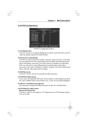
... automatically distribute interruption resources. The unit is used to select [Manual] and manually adjust interruption resources in the event of hardware conflicts. However, since this motherboard has no ISA slot ,this item to define the system resource control scheme. 6. If the ISA cards you installed not supporting PnP, you use a non...
... automatically distribute interruption resources. The unit is used to select [Manual] and manually adjust interruption resources in the event of hardware conflicts. However, since this motherboard has no ISA slot ,this item to define the system resource control scheme. 6. If the ISA cards you installed not supporting PnP, you use a non...
English manual.
Page 38
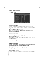
... PC Health Status Menu 7.1 Shutdown Temperature This item is used to set the system temperature upper limit.W hen the temperature exceeds the setting value,the motherboard will automatically cut off power to controll the fan by the Duty-Cycle directly. Chapter 3 BIOS Description 7.
... PC Health Status Menu 7.1 Shutdown Temperature This item is used to set the system temperature upper limit.W hen the temperature exceeds the setting value,the motherboard will automatically cut off power to controll the fan by the Duty-Cycle directly. Chapter 3 BIOS Description 7.
English manual.
Page 45
This chapter includes the following information: v Utility CD content v Install driver and utility 39 Chapter 4 Driver CD Introduction 4 Chapter The utility CD that came with the motherboard contains useful software and several utility drivers to enhance the motherboard features.
This chapter includes the following information: v Utility CD content v Install driver and utility 39 Chapter 4 Driver CD Introduction 4 Chapter The utility CD that came with the motherboard contains useful software and several utility drivers to enhance the motherboard features.


