User manual
Page 5
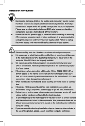
... ! Installation Precautions WARNING! ■ Electrostatic discharge (ESD) is the sudden and momentary electric current that the DC power supply is turned off before installing or removing CPU, memory, expansion cards or other peripherals. tors. ■ If there is recommended to high temperature. It is a PCI Express x16 graphics card installed in order to avoid damage to the motherboard and CPU due to unplug the AC power cord from the power supply...
... ! Installation Precautions WARNING! ■ Electrostatic discharge (ESD) is the sudden and momentary electric current that the DC power supply is turned off before installing or removing CPU, memory, expansion cards or other peripherals. tors. ■ If there is recommended to high temperature. It is a PCI Express x16 graphics card installed in order to avoid damage to the motherboard and CPU due to unplug the AC power cord from the power supply...
User manual
Page 9
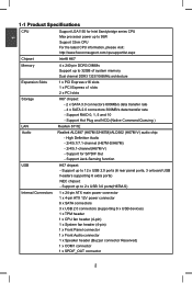
... Expansion Slots 1 x PCI Express x16 slots 1 x PCI Express x1 slots 2 x PCI slots Storage H67 chipset: - 2 x SATA 3.0 connectors 600MB/s data transfer rate - 4 x SATA 2.0 connectors 300MB/s data transfer rate - Support up to 2 x USB 3.0 ports(H67M-S) Internal Connectors 1 x 24-pin ATX main power connector 1 x 4-pin ATX 12V power connector 6 x SATA connectors 3 x USB 2.0 connectors (supporting 6 x USB devices) 1 x TPM header 1 x CPU fan header (4-pin) 1 x System fan header (4-pin) 1 x Front Panel connector 1 x Front Audio connector 1 x Speaker header (Buzzer connector Reserved...
... Expansion Slots 1 x PCI Express x16 slots 1 x PCI Express x1 slots 2 x PCI slots Storage H67 chipset: - 2 x SATA 3.0 connectors 600MB/s data transfer rate - 4 x SATA 2.0 connectors 300MB/s data transfer rate - Support up to 2 x USB 3.0 ports(H67M-S) Internal Connectors 1 x 24-pin ATX main power connector 1 x 4-pin ATX 12V power connector 6 x SATA connectors 3 x USB 2.0 connectors (supporting 6 x USB devices) 1 x TPM header 1 x CPU fan header (4-pin) 1 x System fan header (4-pin) 1 x Front Panel connector 1 x Front Audio connector 1 x Speaker header (Buzzer connector Reserved...
User manual
Page 10
... x Chassis intrusion alarm header (INTR) 1 x CLR_CMOS jumper Back Panel 1 x PS/2 port Connectors 1 x VGA port 1 x DVI-D port 6 x USB 2.0 ports 1 x RJ-45 LAN port 1 x HDMI port (H67M-S/H67M) 2 x USB 3.0 ports (H67M-S) 8-channel Audio ports (H67M-S/H67M) 6-channel Audio ports (H67M-V) Hardware Monitor System voltage detection CPU/System temperature detection CPU/System fan speed detection CPU overheating warning CPU/System fan speed control PCI Express x1 Support 250MB/s (500MB/s concurrent) bandwidth Low power consumption and power management features PCI Express...
... x Chassis intrusion alarm header (INTR) 1 x CLR_CMOS jumper Back Panel 1 x PS/2 port Connectors 1 x VGA port 1 x DVI-D port 6 x USB 2.0 ports 1 x RJ-45 LAN port 1 x HDMI port (H67M-S/H67M) 2 x USB 3.0 ports (H67M-S) 8-channel Audio ports (H67M-S/H67M) 6-channel Audio ports (H67M-V) Hardware Monitor System voltage detection CPU/System temperature detection CPU/System fan speed detection CPU overheating warning CPU/System fan speed control PCI Express x1 Support 250MB/s (500MB/s concurrent) bandwidth Low power consumption and power management features PCI Express...

User manual
Page 14
This chapter introduces the hardware installation process, including the installation of the CPU, memory, power supply, slots, pin headers and the mounting of these modules. Please refer to the motherboard layout prior to any installation and read the contents in this chapter carefully. Caution should be exercised during the installation of jumpers. CPU Support List: http://www.foxconnsupport.com/cpusupportlist.aspx Memory, VGA Compatibility List: http://www.foxconnsupport.com/complist.aspx This...
This chapter introduces the hardware installation process, including the installation of the CPU, memory, power supply, slots, pin headers and the mounting of these modules. Please refer to the motherboard layout prior to any installation and read the contents in this chapter carefully. Caution should be exercised during the installation of jumpers. CPU Support List: http://www.foxconnsupport.com/cpusupportlist.aspx Memory, VGA Compatibility List: http://www.foxconnsupport.com/complist.aspx This...
User manual
Page 20
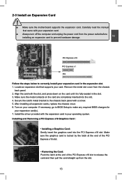
... to BIOS Setup to prevent hardware damage. Installing and Removing a PCI Express x16 Graphics Card : • Installing a Graphics Card: Gently insert the graphics card into the slot. 4. PCI Express x16 PCI Express x1 PCI Follow the steps below to release the card and then pull the card straight up from the chassis back panel. 2. Turn on the card are completely inserted into the PCI Express x16 slot. Make sure the graphics card is fully seated in your expansion card(s). 7. Remove the metal slot...
... to BIOS Setup to prevent hardware damage. Installing and Removing a PCI Express x16 Graphics Card : • Installing a Graphics Card: Gently insert the graphics card into the slot. 4. PCI Express x16 PCI Express x1 PCI Follow the steps below to release the card and then pull the card straight up from the chassis back panel. 2. Turn on the card are completely inserted into the PCI Express x16 slot. Make sure the graphics card is fully seated in your expansion card(s). 7. Remove the metal slot...
User manual
Page 23
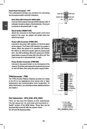
... LED. The fan speed can be automatically turned off . This 2-pin connector is on the front panel of the case; Power LED Connector (PWR-LED) Connect to the power button on the front panel of the chassis. These fans can be turned on this function, you should purchase additional device and install it. When the system is in S3/S4 sleep state or power off mode (S5), the LED is in " Health" section of the hard disks. RESET...
... LED. The fan speed can be automatically turned off . This 2-pin connector is on the front panel of the case; Power LED Connector (PWR-LED) Connect to the power button on the front panel of the chassis. These fans can be turned on this function, you should purchase additional device and install it. When the system is in S3/S4 sleep state or power off mode (S5), the LED is in " Health" section of the hard disks. RESET...
User manual
Page 25
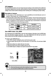
... use the various functions of the jumper settings. Jumper 1 Diagram 1 1 Definition 1-2 2-3 Description Set Pin 1 and Pin 2 closed Set Pin 2 and Pin 3 closed . 4. The steps to temporarily short them. Plug in this motherboard to store the basic hardware information (such as BIOS data, date, time information, hardware password... The shorting can change the jumper settings on this manual, pin 1 is simply labeled as described in next chapter. 3 Clear 2 1 Normal 3 (Default) 2 1 CLR_CMOS WARNING! ■ Disconnect the power cable...
... use the various functions of the jumper settings. Jumper 1 Diagram 1 1 Definition 1-2 2-3 Description Set Pin 1 and Pin 2 closed Set Pin 2 and Pin 3 closed . 4. The steps to temporarily short them. Plug in this motherboard to store the basic hardware information (such as BIOS data, date, time information, hardware password... The shorting can change the jumper settings on this manual, pin 1 is simply labeled as described in next chapter. 3 Clear 2 1 Normal 3 (Default) 2 1 CLR_CMOS WARNING! ■ Disconnect the power cable...
User manual
Page 27
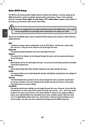
... and software, correctly setting up the BIOS parameters is explained below: Main It displays the basic system configuration, such as less I/O cards, less memory ...etc.), still, it may offer better performance in some ways (such as CPU Name, memory size, system date, time and so on the computer, when the message "Press to enter Setup, to Boot Menu" appears at the bottom of the screen, you...
... and software, correctly setting up the BIOS parameters is explained below: Main It displays the basic system configuration, such as less I/O cards, less memory ...etc.), still, it may offer better performance in some ways (such as CPU Name, memory size, system date, time and so on the computer, when the message "Press to enter Setup, to Boot Menu" appears at the bottom of the screen, you...

User manual
Page 31
...: Save & Exit ESC: Exit Version 2.02.1205. Default option is used to decide whether to support TPM (Trusted Platform Module) device function. If you want to support TPM, first you need to install a TPM device on the motherboard and set this item to +500.0mV. Trusted Computing Aptio Setup Utility - 3 incremented from +12.5mV to [Enabled], then save changing and reset your computer, otherwise the operation...
...: Save & Exit ESC: Exit Version 2.02.1205. Default option is used to decide whether to support TPM (Trusted Platform Module) device function. If you want to support TPM, first you need to install a TPM device on the motherboard and set this item to +500.0mV. Trusted Computing Aptio Setup Utility - 3 incremented from +12.5mV to [Enabled], then save changing and reset your computer, otherwise the operation...

User manual
Page 32
.... Replacing older computers with anti-virus, firewall, spyware removal, e-mail filtering software, and other network security measures, IT managers can free IT resources for virus-related repairs. Intel's Execute Disable Bit functionality can halt worm attacks, reducing the need for other initiatives. ► Intel Virtualization Technology (Appears only when CPU supports) Virtualization (i.e. C opyright (C) 2010 American Megatrends, Inc. CPU Configuration Aptio Setup Utility - This item is used to enable/disable the...
.... Replacing older computers with anti-virus, firewall, spyware removal, e-mail filtering software, and other network security measures, IT managers can free IT resources for virus-related repairs. Intel's Execute Disable Bit functionality can halt worm attacks, reducing the need for other initiatives. ► Intel Virtualization Technology (Appears only when CPU supports) Virtualization (i.e. C opyright (C) 2010 American Megatrends, Inc. CPU Configuration Aptio Setup Utility - This item is used to enable/disable the...

User manual
Page 35
USB Configuration Aptio Setup Utility - Advanced USB Configuration USB Devices: 2 Hubs Enabled/Disabled All USB Devices All USB Devices Legacy USB Support [Enabled] [Enabled] → ← : Select Screen ↑ ↓ : Select Item Enter: Select +/-: Change Opt. Copyright (C) 2010 American Megatrends, Inc. ► All USB Devices This item is used to comply with FCC regulation. But if overclocking is used to enable or disable the support for USB devices. ► Legacy USB Support This item is activated, you better disable it can significantly reduce ...
USB Configuration Aptio Setup Utility - Advanced USB Configuration USB Devices: 2 Hubs Enabled/Disabled All USB Devices All USB Devices Legacy USB Support [Enabled] [Enabled] → ← : Select Screen ↑ ↓ : Select Item Enter: Select +/-: Change Opt. Copyright (C) 2010 American Megatrends, Inc. ► All USB Devices This item is used to comply with FCC regulation. But if overclocking is used to enable or disable the support for USB devices. ► Legacy USB Support This item is activated, you better disable it can significantly reduce ...
User manual
Page 36
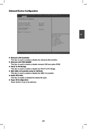
...Configuration Azalia HD Audio [Enabled] ▶ Super IO Configuration → ← : Select Screen ↑ ↓ : Select Item Enter: Select +/-: Change Opt. 3 Onboard Device Configuration Aptio Setup Utility - Copyright (C) 2010 American Megatrends, Inc. ► Onboard LAN Controller This item is used to enable or disable the onboard LAN controller. ► Onboard LAN PXE OpROM This item is used to enable or disable onboard LAN boot option ROM. ► PCI-E To PCI Bridge This item is used to enable or disable the PCI-E To PCI Bridge. ► NEC USB 3.0 Controller (only for H67M...
...Configuration Azalia HD Audio [Enabled] ▶ Super IO Configuration → ← : Select Screen ↑ ↓ : Select Item Enter: Select +/-: Change Opt. 3 Onboard Device Configuration Aptio Setup Utility - Copyright (C) 2010 American Megatrends, Inc. ► Onboard LAN Controller This item is used to enable or disable the onboard LAN controller. ► Onboard LAN PXE OpROM This item is used to enable or disable onboard LAN boot option ROM. ► PCI-E To PCI Bridge This item is used to enable or disable the PCI-E To PCI Bridge. ► NEC USB 3.0 Controller (only for H67M...
User manual
Page 45
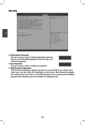
... item is used to install or change administrator password. C opyright (C) 2010 American Megatrends, Inc. Main Advanced Chipset Boot Power Health Security Save & Exit Password Description If ONLY the Administrator's password is set , then this only limits access to Setup and is a power on the item "HDD 0:ST3160815AS" to set, modify and clear HardDisk password. Set Setup Administrator Password Administrator Password User Password HDD Security Configuration HDD 0:ST3160815AS → ← : Select Screen ↑ ↓ : Select Item Enter: Select +/-: Change Opt...
... item is used to install or change administrator password. C opyright (C) 2010 American Megatrends, Inc. Main Advanced Chipset Boot Power Health Security Save & Exit Password Description If ONLY the Administrator's password is set , then this only limits access to Setup and is a power on the item "HDD 0:ST3160815AS" to set, modify and clear HardDisk password. Set Setup Administrator Password Administrator Password User Password HDD Security Configuration HDD 0:ST3160815AS → ← : Select Screen ↑ ↓ : Select Item Enter: Select +/-: Change Opt...

User manual
Page 48
... VGA Driver D. Intel LAN Driver F. FOX ONE C. USB 3.0 Driver 2. FOX DMI F. FOX LiveUpdate D. 4 Utility CD content This motherboard comes with one Utility CD. Realtek HDA Audio Driver E. Adobe Acrobat Reader G. Intel Chipset Driver C. FOX DMI F. Adobe Acrobat Reader H. Some auto features help user to BIOS. Intel Management Engine Driver B. FOX LOGO E. Install Driver Use these options to install additional software programs. FOX ONE is a very powerful user interface program which allows you to change your system setting...
... VGA Driver D. Intel LAN Driver F. FOX ONE C. USB 3.0 Driver 2. FOX DMI F. FOX LiveUpdate D. 4 Utility CD content This motherboard comes with one Utility CD. Realtek HDA Audio Driver E. Adobe Acrobat Reader G. Intel Chipset Driver C. FOX DMI F. Adobe Acrobat Reader H. Some auto features help user to BIOS. Intel Management Engine Driver B. FOX LOGO E. Install Driver Use these options to install additional software programs. FOX ONE is a very powerful user interface program which allows you to change your system setting...

User manual
Page 49
... program Visit Foxconn's Show Utilities Show Drivers Browse CD View the Utility Website Help files Choose the items you how to install it manually. 4 Install driver and utility This motherboard comes with one DVD, after installing the Operating System, you can click on your system. You must click "Intel Chipset Driver" to install it into your DVD-ROM drive, and the main menu will be displayed on each individual driver to install. 1. After that...
... program Visit Foxconn's Show Utilities Show Drivers Browse CD View the Utility Website Help files Choose the items you how to install it manually. 4 Install driver and utility This motherboard comes with one DVD, after installing the Operating System, you can click on your system. You must click "Intel Chipset Driver" to install it into your DVD-ROM drive, and the main menu will be displayed on each individual driver to install. 1. After that...
User manual
Page 80
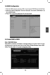
... save the setting then PC will display a message asking you to press + keys simultaneously to Non-RAID 2. Reset Disks to enter the main menu of Intel® Matrix Storage Manager Option ROM Utility. Enter the BIOS setup by pressing key during the POST(Power On Self Test). 2. Option ROM - 10.0.0.1032 Copyright(C) 2003-10 Intel Corporation. C opyright (C) 2010 American Megatrends, Inc. Advanced SATA Configuration SATA Mode [RAID Mode] (1) IDE Mode. (2) AHCI Mode. (3) RAID Mode. All Rights Reserved. [ MAIN MENU ] 1. Delete RAID Volume 4. SATA Port1 Not...
... save the setting then PC will display a message asking you to press + keys simultaneously to Non-RAID 2. Reset Disks to enter the main menu of Intel® Matrix Storage Manager Option ROM Utility. Enter the BIOS setup by pressing key during the POST(Power On Self Test). 2. Option ROM - 10.0.0.1032 Copyright(C) 2003-10 Intel Corporation. C opyright (C) 2010 American Megatrends, Inc. Advanced SATA Configuration SATA Mode [RAID Mode] (1) IDE Mode. (2) AHCI Mode. (3) RAID Mode. All Rights Reserved. [ MAIN MENU ] 1. Delete RAID Volume 4. SATA Port1 Not...
User manual
Page 105
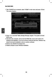
..., select "5. The system will continue for Windows OS installation. Remove any diskette from floppy drive. 5. Exit RAID BIOS 1. Reset Disks to exit Intel® Matrix Storage Manager program. Press to Non-RAID 2. If you do not remove irrelevant hard disk, Windows may detect it during the installation, and you want to start Windows installation. 5 98 Restart computer to exit? Exit" in main menu and press . The screen displays : Intel(RIn) tMela(Rtr)ixRSatpoirdagSetoMraagneaTgeecrhonpotilongyR...
..., select "5. The system will continue for Windows OS installation. Remove any diskette from floppy drive. 5. Exit RAID BIOS 1. Reset Disks to exit Intel® Matrix Storage Manager program. Press to Non-RAID 2. If you do not remove irrelevant hard disk, Windows may detect it during the installation, and you want to start Windows installation. 5 98 Restart computer to exit? Exit" in main menu and press . The screen displays : Intel(RIn) tMela(Rtr)ixRSatpoirdagSetoMraagneaTgeecrhonpotilongyR...
User manual
Page 106
... you set the SATA Mode in BIOS to either AHCI or RAID, you need to CD/DVD ROM, save changes and exit the BIOS setup. F1: General Help F2: Previous Values F3: Optimized Defaults F4: Save & Exit ESC: Exit Version 2.02.1205. PC may need to follow these steps to do this, PC will start installing Windows Operating System. Aptio Setup Utility - Main Advanced Chipset Boot Power Health Security Save & Exit Boot Configuration Bootup...
... you set the SATA Mode in BIOS to either AHCI or RAID, you need to CD/DVD ROM, save changes and exit the BIOS setup. F1: General Help F2: Previous Values F3: Optimized Defaults F4: Save & Exit ESC: Exit Version 2.02.1205. PC may need to follow these steps to do this, PC will start installing Windows Operating System. Aptio Setup Utility - Main Advanced Chipset Boot Power Health Security Save & Exit Boot Configuration Bootup...

User manual
Page 107
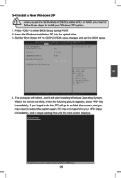
... the specific driver installation. It will load support for use with Windows, press ENTER. After some files are copied to your system, or you have any device support disks from a mass storage device manufacturer, press S. * If you have a device support disk from a mass storage device manufacturer, or do not have chosen to insert the RAID driver diskette into Drive A: * Press ENTER when ready ENTER=Continue ESC=Cancel F3=Exit 100 Currently, Setup will ask you floppy drive...
... the specific driver installation. It will load support for use with Windows, press ENTER. After some files are copied to your system, or you have any device support disks from a mass storage device manufacturer, press S. * If you have a device support disk from a mass storage device manufacturer, or do not have chosen to insert the RAID driver diskette into Drive A: * Press ENTER when ready ENTER=Continue ESC=Cancel F3=Exit 100 Currently, Setup will ask you floppy drive...
User manual
Page 109
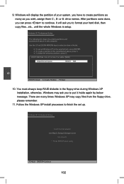
... the list. ● To set up Windows XP on the selected item, press ENTER. ● To create a partition in the floppy drive during Windows XP installation, otherwise, Windows may copy files from the floppy drive, please remember. 11. Windows XP Professional Setup Insert the disk labeled: Intel Matrix Storage Manager driver into drive A: * Press ENTER when ready F3=Quit ENTER=Continue 102 It will display the partition of your hard disk, then copy files...
... the list. ● To set up Windows XP on the selected item, press ENTER. ● To create a partition in the floppy drive during Windows XP installation, otherwise, Windows may copy files from the floppy drive, please remember. 11. Windows XP Professional Setup Insert the disk labeled: Intel Matrix Storage Manager driver into drive A: * Press ENTER when ready F3=Quit ENTER=Continue 102 It will display the partition of your hard disk, then copy files...


