
User manual
Page 1
H61MXV/H67MXV Series Motherboard User's Manual
H61MXV/H67MXV Series Motherboard User's Manual
User manual
Page 2
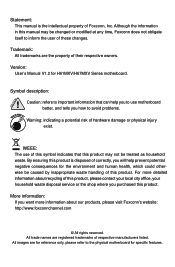
..., your household waste disposal service or the shop where you want more detailed information about our products, please visit Foxconn's website: http://www.foxconnchannel.com © All rights reserved. Trademark: All trademarks are the property of respective manufacturers... disposed of these changes. Symbol description: ! WEEE: The use motherboard better, and tells you will help you to the physical motherboard for H61MXV/H67MXV Series motherboard. For more information about recycling of Foxconn, Inc. More information: If you purchased this manual may exist...
..., your household waste disposal service or the shop where you want more detailed information about our products, please visit Foxconn's website: http://www.foxconnchannel.com © All rights reserved. Trademark: All trademarks are the property of respective manufacturers... disposed of these changes. Symbol description: ! WEEE: The use motherboard better, and tells you will help you to the physical motherboard for H61MXV/H67MXV Series motherboard. For more information about recycling of Foxconn, Inc. More information: If you purchased this manual may exist...
User manual
Page 3
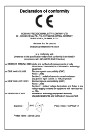
... information technology equipment ■ EN 61000-3-2/:2000 Electromagnetic compatibility (EMC) Part 3: Limits Section 2: Limits for harmonic current emissions (equipment input current declares that the product Motherboard H61MXV/H67MXV is in conformity with (reference to the specification under which conformity is declared in accordance with 89/336 EEC-EMC Directive) ■ EN 55022...
... information technology equipment ■ EN 61000-3-2/:2000 Electromagnetic compatibility (EMC) Part 3: Limits Section 2: Limits for harmonic current emissions (equipment input current declares that the product Motherboard H61MXV/H67MXV is in conformity with (reference to the specification under which conformity is declared in accordance with 89/336 EEC-EMC Directive) ■ EN 55022...
User manual
Page 4
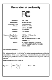
... undesired operation. Supplementary Information: This device complies with FCC standards. Signature : Date : 2012 Declaration of Product: Manufacturer: Address: FCC Class B Subassembly Motherboard HON HAI PRECISION INDUSTRY COMPANY LTD 66 , CHUNG SHAN RD., TU-CHENG INDUSTRIAL DISTRICT, TAIPEI HSIEN, TAIWAN, R.O.C. Operation is subject to comply with ...92835 714-738-8868 714-738-8838 Equipment Classification: Type of conformity Trade Name: Model Name: Responsible Party: Address: Telephone: Facsimile: FOXCONN H61MXV/H67MXV PCE Industry Inc. 458 E. Lambert Rd.
... undesired operation. Supplementary Information: This device complies with FCC standards. Signature : Date : 2012 Declaration of Product: Manufacturer: Address: FCC Class B Subassembly Motherboard HON HAI PRECISION INDUSTRY COMPANY LTD 66 , CHUNG SHAN RD., TU-CHENG INDUSTRIAL DISTRICT, TAIPEI HSIEN, TAIWAN, R.O.C. Operation is subject to comply with ...92835 714-738-8868 714-738-8838 Equipment Classification: Type of conformity Trade Name: Model Name: Responsible Party: Address: Telephone: Facsimile: FOXCONN H61MXV/H67MXV PCE Industry Inc. 458 E. Lambert Rd.
User manual
Page 5
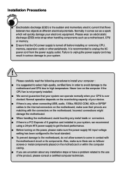
...connectors. ■ If there is a PCI Express x16 graphics card installed in your system. ! Incorrect connections might damage the motherboard. ■ When handling the motherboard, avoid touching any installation steps or have a problem related to your system, we recommend using a 24-pin ATX power supply...wrist strap when handling components such as a spark which will quickly damage your CPU is over clocked. Normally it comes out as a motherboard, CPU or memory. ■ Ensure that flows between two objects at different electrical potentials. Also, make sure the power supply AC ...
...connectors. ■ If there is a PCI Express x16 graphics card installed in your system. ! Incorrect connections might damage the motherboard. ■ When handling the motherboard, avoid touching any installation steps or have a problem related to your system, we recommend using a 24-pin ATX power supply...wrist strap when handling components such as a spark which will quickly damage your CPU is over clocked. Normally it comes out as a motherboard, CPU or memory. ■ Ensure that flows between two objects at different electrical potentials. Also, make sure the power supply AC ...

User manual
Page 8
Foxconn products are engineered to maximize computing power, providing only what you to unleash more power from your computer. This chapter includes the following information Product Specifications ■ Layout ■ Back Panel Connectors With advanced overclocking capability and a range of connectivity features for today multi-media computing requirements, H61MXV/ H67MXV enables you need for buying Foxconn H61MXV/H67MXV Series motherboard. Thank you for break-through performance.
Foxconn products are engineered to maximize computing power, providing only what you to unleash more power from your computer. This chapter includes the following information Product Specifications ■ Layout ■ Back Panel Connectors With advanced overclocking capability and a range of connectivity features for today multi-media computing requirements, H61MXV/ H67MXV enables you need for buying Foxconn H61MXV/H67MXV Series motherboard. Thank you for break-through performance.
User manual
Page 11
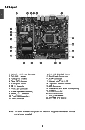
... USB Connectors 11. PCH_ME_ENABLE Jumper 13. Chassis intrusion alarm header (INTR) 19. DDR3 DIMM Slots 21. CPU_FAN Header 22. LGA1155 CPU Socket Note : The above motherboard layout is for reference only, please refer to the physical...
... USB Connectors 11. PCH_ME_ENABLE Jumper 13. Chassis intrusion alarm header (INTR) 19. DDR3 DIMM Slots 21. CPU_FAN Header 22. LGA1155 CPU Socket Note : The above motherboard layout is for reference only, please refer to the physical...
User manual
Page 14
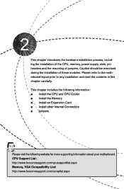
... Card ■ Install other Internal Connectors ■ Jumpers Please visit the following website for more supporting information about your motherboard. Caution should be exercised during the installation of jumpers. CPU Support List: http://www.foxconnsupport.com/cpusupportlist.aspx Memory, ...VGA Compatibility List: http://www.foxconnsupport.com/complist.aspx Please refer to the motherboard layout prior to any installation and read the contents in this chapter carefully. This chapter introduces the hardware installation ...
... Card ■ Install other Internal Connectors ■ Jumpers Please visit the following website for more supporting information about your motherboard. Caution should be exercised during the installation of jumpers. CPU Support List: http://www.foxconnsupport.com/cpusupportlist.aspx Memory, ...VGA Compatibility List: http://www.foxconnsupport.com/complist.aspx Please refer to the motherboard layout prior to any installation and read the contents in this chapter carefully. This chapter introduces the hardware installation ...
User manual
Page 15
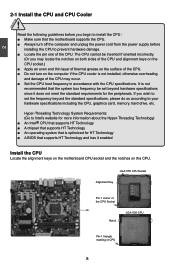
The CPU cannot be set the frequency beyond hardware specifications since it enabled Install the CPU Locate the alignment keys on the motherboard CPU socket and the notches on the CPU. Hyper-Threading Technology System Requirements: (Go to Intel's website for more information about the ...oriented incorrectly. (Or you may occur. ■ Set the CPU host frequency in accordance with the CPU specifications. It is not recommended that the motherboard supports the CPU. ■ Always turn on the computer if the CPU cooler is optimized for HT Technology ■ A BIOS that supports HT...
The CPU cannot be set the frequency beyond hardware specifications since it enabled Install the CPU Locate the alignment keys on the motherboard CPU socket and the notches on the CPU. Hyper-Threading Technology System Requirements: (Go to Intel's website for more information about the ...oriented incorrectly. (Or you may occur. ■ Set the CPU host frequency in accordance with the CPU specifications. It is not recommended that the motherboard supports the CPU. ■ Always turn on the computer if the CPU cooler is optimized for HT Technology ■ A BIOS that supports HT...
User manual
Page 17
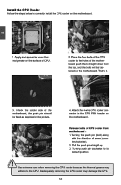
... CPU cooler because the thermal grease may damage the CPU. 10 Inadequately removing the CPU cooler may adhere to the CPU FAN header on the motherboard . 3 2 1 Release bolts of CPU cooler from the top, and the bolts will be fixed as depicted in the picture. 4. Place the four ... the steps below to its default position. ! Turning push pin clockwise to correctly install the CPU cooler on the motherboard. Apply and spread an even thermal grease on the surface of the motherboard, push them straight down from motherboard : 1.Turning the push pin (bolt) along with the direction of the...
... CPU cooler because the thermal grease may damage the CPU. 10 Inadequately removing the CPU cooler may adhere to the CPU FAN header on the motherboard . 3 2 1 Release bolts of CPU cooler from the top, and the bolts will be fixed as depicted in the picture. 4. Place the four ... the steps below to its default position. ! Turning push pin clockwise to correctly install the CPU cooler on the motherboard. Apply and spread an even thermal grease on the surface of the motherboard, push them straight down from motherboard : 1.Turning the push pin (bolt) along with the direction of the...
User manual
Page 18
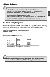
Dual Channel Memory Configuration This motherboard provides two DDR3 memory sockets and supports Dual Channel Technology. DS/SS Dual Channel DS/SS DS/SS (DS : Double Side, SS : Single Side, - : No ... the computer and unplug the power cord from the power outlet before you are : Single Channel DIMM1 DS/SS DIMM2 - It is recommended that the motherboard supports the memory. CAUTION 2 2-2 Install the Memory ! Read the following guidelines before installing the memory to insert the memory, switch the direction.
Dual Channel Memory Configuration This motherboard provides two DDR3 memory sockets and supports Dual Channel Technology. DS/SS Dual Channel DS/SS DS/SS (DS : Double Side, SS : Single Side, - : No ... the computer and unplug the power cord from the power outlet before you are : Single Channel DIMM1 DS/SS DIMM2 - It is recommended that the motherboard supports the memory. CAUTION 2 2-2 Install the Memory ! Read the following guidelines before installing the memory to insert the memory, switch the direction.
User manual
Page 19
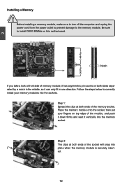
..., so it can only fit in one direction. 2 CAUTION 144-Pin 96-Pin Installing a Memory ! Follow the steps below to install DDR3 DIMMs on this motherboard. Step 1: Spread the clips at both ends of the memory socket. Before installing a memory module, make sure to turn off the computer and unplug the...
..., so it can only fit in one direction. 2 CAUTION 144-Pin 96-Pin Installing a Memory ! Follow the steps below to install DDR3 DIMMs on this motherboard. Step 1: Spread the clips at both ends of the memory socket. Before installing a memory module, make sure to turn off the computer and unplug the...
User manual
Page 20
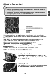
CAUTION 2 2-3 Install an Expansion Card ! ■ Make sure the motherboard supports the expansion card. PCI Express x16 PCI Express x1 Follow the steps below to correctly install your operating system. After installing all expansion cards, ...
CAUTION 2 2-3 Install an Expansion Card ! ■ Make sure the motherboard supports the expansion card. PCI Express x16 PCI Express x1 Follow the steps below to correctly install your operating system. After installing all expansion cards, ...
User manual
Page 21
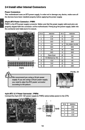
... 24 GND 12 PWR1 1 ! We recommend you using a 20-pin power supply, you are properly aligned with the connector on the motherboard. 2 CAUTION 2-4 Install other Internal Connectors Power Connectors This motherboard uses an ATX power supply. In order not to the CPU. +12V 3 1 4 2 PWR2 GND Pin # 1 2 3 4 Definition GND GND +12V +12V 14...
... 24 GND 12 PWR1 1 ! We recommend you using a 20-pin power supply, you are properly aligned with the connector on the motherboard. 2 CAUTION 2-4 Install other Internal Connectors Power Connectors This motherboard uses an ATX power supply. In order not to the CPU. +12V 3 1 4 2 PWR2 GND Pin # 1 2 3 4 Definition GND GND +12V +12V 14...
User manual
Page 22
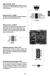
... II interface allows up to 300MB/s data transfer rate. By connecting through the function of this product also provides 10-pin USB headers on its motherboard. Audio Connector : F_AUDIO The audio connector supports HD Audio standard. The system can detect the chassis intrusion through USB cables with SATA Hard Disk or...
... II interface allows up to 300MB/s data transfer rate. By connecting through the function of this product also provides 10-pin USB headers on its motherboard. Audio Connector : F_AUDIO The audio connector supports HD Audio standard. The system can detect the chassis intrusion through USB cables with SATA Hard Disk or...
User manual
Page 23
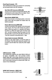
...PDIF output. 16 +5V 1 EMPTY 2 SPDIF_OUT 3 GND 4 SPDIF_OUT This 2pin connector is on and off . 2 Front Panel Connector : FP1 This motherboard includes one serial RS232 COM port for legacy compatibility. sign. It indicates the active status of the case; PWR-LED - Reset Switch (RESET-SW) Attach...LED. the system will restart when the switch is blinking; RESET-SW PWR-SW NC EMPTY 9 10 FP1 COM Connector : COM2 This motherboard supports one connector for connecting the front panel switch and LED Indicators. When the system is in operation (S0 status), the LED is...
...PDIF output. 16 +5V 1 EMPTY 2 SPDIF_OUT 3 GND 4 SPDIF_OUT This 2pin connector is on and off . 2 Front Panel Connector : FP1 This motherboard includes one serial RS232 COM port for legacy compatibility. sign. It indicates the active status of the case; PWR-LED - Reset Switch (RESET-SW) Attach...LED. the system will restart when the switch is blinking; RESET-SW PWR-SW NC EMPTY 9 10 FP1 COM Connector : COM2 This motherboard supports one connector for connecting the front panel switch and LED Indicators. When the system is in operation (S0 status), the LED is...

User manual
Page 24
To utilize this motherboard. These fans can be automatically turned off after the system enter S3, S4 and S5 sleeping states. 12 LCLK LFRAMEn LRESETn LAD3 VDD LAD0 NC_1 ...
To utilize this motherboard. These fans can be automatically turned off after the system enter S3, S4 and S5 sleeping states. 12 LCLK LFRAMEn LRESETn LAD3 VDD LAD0 NC_1 ...
User manual
Page 25
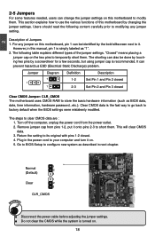
...to short them. Remove jumper cap from the power outlet. 2. Normal 1 2 (Default) 3 1 Clear 2 3 WARNING! "Closed" means placing a jumper cap on this motherboard by the bold silkscreen next to it on . 18 Jumper Diagram Definition Description 1 1 1 1-2 Set Pin 1 and Pin 2 closed 2-3 Set Pin 2 and...content carefully prior to modifying any jumper on this manual, pin 1 is recommended. Clear CMOS data is turned on . 5. Plug in this motherboard, pin 1 can be done by touching two pins by a screwdriver for a few seconds, but using jumper cap is simply labeled as ...
...to short them. Remove jumper cap from the power outlet. 2. Normal 1 2 (Default) 3 1 Clear 2 3 WARNING! "Closed" means placing a jumper cap on this motherboard by the bold silkscreen next to it on . 18 Jumper Diagram Definition Description 1 1 1 1-2 Set Pin 1 and Pin 2 closed 2-3 Set Pin 2 and...content carefully prior to modifying any jumper on this manual, pin 1 is recommended. Clear CMOS data is turned on . 5. Plug in this motherboard, pin 1 can be done by touching two pins by a screwdriver for a few seconds, but using jumper cap is simply labeled as ...

User manual
Page 26
... the jumper to pins 1-2, you can enable the Intel® Management Engine function. Set the jumper to pins 2-3 first. 2 Intel® ME Jumper: PCH_ME_ENABLE This motherboard uses PCH_ME_ENABLE jumper to improve management of corporate assets. It provides latest IT management features such as Intel® AMT, that allows to enable or...
... the jumper to pins 1-2, you can enable the Intel® Management Engine function. Set the jumper to pins 2-3 first. 2 Intel® ME Jumper: PCH_ME_ENABLE This motherboard uses PCH_ME_ENABLE jumper to improve management of corporate assets. It provides latest IT management features such as Intel® AMT, that allows to enable or...
User manual
Page 32
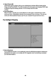
... [F7] key to comply with FCC regulation. Fox Intelligent Stepping Aptio Setup Utility - 3 ► Smart Power LED Smart Power LED is a feature built on your motherboard to get into your computer through smart boot menu.
... [F7] key to comply with FCC regulation. Fox Intelligent Stepping Aptio Setup Utility - 3 ► Smart Power LED Smart Power LED is a feature built on your motherboard to get into your computer through smart boot menu.


