
User manual
Page 9
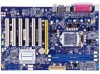
...rate) Asmedia ASM1061: - 2 x SATA 3.0 connectors (6Gb/s data transfer rate) (only for H61AP-S) LAN Realtek 8111F Gigabit LAN chip Support 10/100/1000Mbps Audio Realtek ALC662 Audio chip: -High Definition Audio -2/4/5.1-channel -Support for SPDIF Out -Support Jack-Sensing function USB Support up to 10 x ...USB 2.0 ports (4 rear panel ports, 3 onboard USB headers supporting 6 extra ports) (H61AP) Support up to 8 x USB 2.0 ports...
...rate) Asmedia ASM1061: - 2 x SATA 3.0 connectors (6Gb/s data transfer rate) (only for H61AP-S) LAN Realtek 8111F Gigabit LAN chip Support 10/100/1000Mbps Audio Realtek ALC662 Audio chip: -High Definition Audio -2/4/5.1-channel -Support for SPDIF Out -Support Jack-Sensing function USB Support up to 10 x ...USB 2.0 ports (4 rear panel ports, 3 onboard USB headers supporting 6 extra ports) (H61AP) Support up to 8 x USB 2.0 ports...
User manual
Page 13
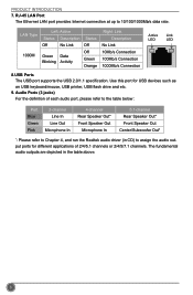
Audio Ports (3 jacks) For the definition of each audio port, please refer to the table below : Port Blue Green Pink 2-channel Line In Line Out Microphone In 4-channel Rear Speaker Out* ...
Audio Ports (3 jacks) For the definition of each audio port, please refer to the table below : Port Blue Green Pink 2-channel Line In Line Out Microphone In 4-channel Rear Speaker Out* ...
User manual
Page 21
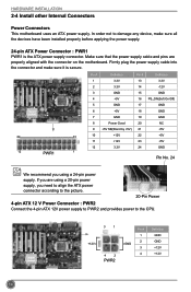
Pin # Definition Pin # Definition 1 3.3V 13 3.3V 2 3.3V 14 -12V 3 GND 15 GND 4 +5V 16 PS_ON(Soft On/Off) 5 GND 17 GND 6 +5V 18 GND 7 GND 19 GND 8 Power ... properly before applying the power supply. 24-pin ATX Power Connector : PWR1 PWR1 is secure. In order not to the CPU. +12V 3 1 4 2 PWR2 GND Pin # 1 2 3 4 Definition GND GND +12V +12V 14 Make sure that the power supply cable and pins are using a 24-pin power supply. HARDWARE INSTALLATION 2-4 Install other Internal...
Pin # Definition Pin # Definition 1 3.3V 13 3.3V 2 3.3V 14 -12V 3 GND 15 GND 4 +5V 16 PS_ON(Soft On/Off) 5 GND 17 GND 6 +5V 18 GND 7 GND 19 GND 8 Power ... properly before applying the power supply. 24-pin ATX Power Connector : PWR1 PWR1 is secure. In order not to the CPU. +12V 3 1 4 2 PWR2 GND Pin # 1 2 3 4 Definition GND GND +12V +12V 14 Make sure that the power supply cable and pins are using a 24-pin power supply. HARDWARE INSTALLATION 2-4 Install other Internal...
User manual
Page 25
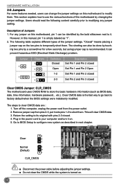
... to temporarily short them . However, in this motherboard by the bold silkscreen next to short them. Clear CMOS data is simply labeled as "1". 2. Jumper 1 1 Diagram 1 1 1 1 Definition Closed Open 1-2 2-3 Description Set Pin 1 and Pin 2 closed Set Pin 1 and Pin 2 Open Set Pin 1 and Pin 2 closed Set Pin 2 and Pin 3 closed . 4. Return the...
... to temporarily short them . However, in this motherboard by the bold silkscreen next to short them. Clear CMOS data is simply labeled as "1". 2. Jumper 1 1 Diagram 1 1 1 1 Definition Closed Open 1-2 2-3 Description Set Pin 1 and Pin 2 closed Set Pin 1 and Pin 2 Open Set Pin 1 and Pin 2 closed Set Pin 2 and Pin 3 closed . 4. Return the...
User manual
Page 26
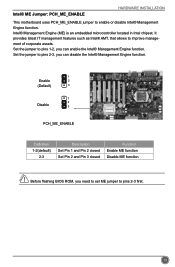
... the jumper to pins 2-3, you need to set ME jumper to pins 1-2, you can disable the Intel® Management Engine function. 1 Enable 2 (Default) 3 1 2 Disable 3 PCH_ME_ENABLE Definition 1-2(default) 2-3 Description Set Pin 1 and Pin 2 closed Set Pin 2 and Pin 3 closed Function Enable ME function Disable ME function CAUTION Before flashing BIOS ROM, you...
... the jumper to pins 2-3, you need to set ME jumper to pins 1-2, you can disable the Intel® Management Engine function. 1 Enable 2 (Default) 3 1 2 Disable 3 PCH_ME_ENABLE Definition 1-2(default) 2-3 Description Set Pin 1 and Pin 2 closed Set Pin 2 and Pin 3 closed Function Enable ME function Disable ME function CAUTION Before flashing BIOS ROM, you...