English Manual.
Page 5
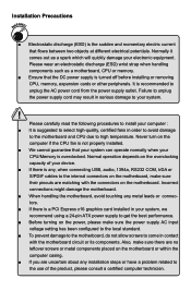
... recommend using a 24-pin ATX power supply to get the best performance. ■ Before turning on the power, please make sure the power supply AC input voltage setting has been configured to the local standard. ■ To prevent damage to the motherboard, do not allow screws to the use of your device. ■ If there is a PCI Express x16 graphics card installed in contact with the connectors on the overclocking capacity of...
... recommend using a 24-pin ATX power supply to get the best performance. ■ Before turning on the power, please make sure the power supply AC input voltage setting has been configured to the local standard. ■ To prevent damage to the motherboard, do not allow screws to the use of your device. ■ If there is a PCI Express x16 graphics card installed in contact with the connectors on the overclocking capacity of...
English Manual.
Page 9
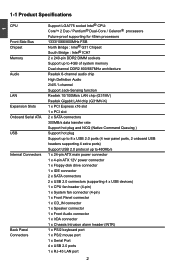
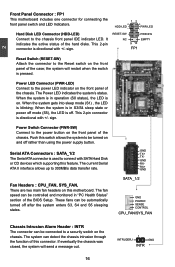
... Internal Connectors 1 x 24-pin ATX main power connector 1 x 4-pin ATX 12V power connector 1 x Floppy disk drive connector 1 x IDE connector 2 x SATA connectors 2 x USB 2.0 connectors (supporting 4 x USB devices) 1 x CPU fan header (4-pin) 1 x System fan connector (4-pin) 1 x Front Panel connector 1 x CD_IN connector 1 x Speaker connector 1 x Front Audio connector 1 x IrDA connector 1 x Chassis Intrusion alarm header (INTR) Back Panel 1 x PS/2 keyboard port Connectors 1 x PS/2 mouse port 1 x Serial Port 4 x USB 2.0 ports 1 x RJ-45 LAN port...
... Internal Connectors 1 x 24-pin ATX main power connector 1 x 4-pin ATX 12V power connector 1 x Floppy disk drive connector 1 x IDE connector 2 x SATA connectors 2 x USB 2.0 connectors (supporting 4 x USB devices) 1 x CPU fan header (4-pin) 1 x System fan connector (4-pin) 1 x Front Panel connector 1 x CD_IN connector 1 x Speaker connector 1 x Front Audio connector 1 x IrDA connector 1 x Chassis Intrusion alarm header (INTR) Back Panel 1 x PS/2 keyboard port Connectors 1 x PS/2 mouse port 1 x Serial Port 4 x USB 2.0 ports 1 x RJ-45 LAN port...
English Manual.
Page 20
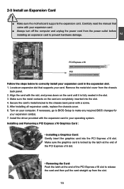
... PCI Express x16 slot. PCI Express x16 PCI Follow the steps below to the chassis back panel with your operating system. Make sure the metal contacts on your expansion card in your expansion card. ■ Always turn off the computer and unplug the power cord from the chassis back panel. 2. After installing all expansion cards, replace the chassis cover. 6. CAUTION 2 2-3 Install an Expansion Card ! ■ Make sure the motherboard supports the expansion card...
... PCI Express x16 slot. PCI Express x16 PCI Follow the steps below to the chassis back panel with your operating system. Make sure the metal contacts on your expansion card in your expansion card. ■ Always turn off the computer and unplug the power cord from the chassis back panel. 2. After installing all expansion cards, replace the chassis cover. 6. CAUTION 2 2-3 Install an Expansion Card ! ■ Make sure the motherboard supports the expansion card...
English Manual.
Page 23
...-LED) Connect to the power LED indicator on the front panel of the BIOS Setup. When the system is in operation (S0 status), the LED is on the front panel of the hard disks. This 2-pin connector is directional with +/- Serial ATA Connectors : SATA_1/2 The Serial ATA connector is off mode (S5), the LED is used to the power button on . The fan speed can be controlled and monitored in "PC Health Status" section of the chassis. SATA...
...-LED) Connect to the power LED indicator on the front panel of the BIOS Setup. When the system is in operation (S0 status), the LED is on the front panel of the hard disks. This 2-pin connector is directional with +/- Serial ATA Connectors : SATA_1/2 The Serial ATA connector is off mode (S5), the LED is used to the power button on . The fan speed can be controlled and monitored in "PC Health Status" section of the chassis. SATA...
English Manual.
Page 24
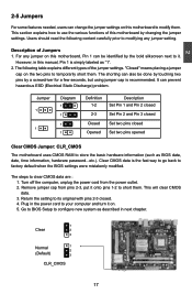
... . The shorting can prevent hazardous ESD (Electrical Static Discharge) problem. Return the setting to its original with pins 2-3 closed Set two pins opened Clear CMOS Jumper: CLR_CMOS The motherboard uses CMOS RAM to configure new system as BIOS data, date, time information, hardware password...etc.). Jumper 1 1 Diagram 1 1 1 1 Definition 1-2 2-3 Closed Opened Description Set Pin 1 and Pin 2 closed Set Pin 2 and Pin 3 closed Set two pins closed . 4. This will clear CMOS data. 3. Remove jumper cap from the power outlet. 2. Go to BIOS Setup to store...
... . The shorting can prevent hazardous ESD (Electrical Static Discharge) problem. Return the setting to its original with pins 2-3 closed Set two pins opened Clear CMOS Jumper: CLR_CMOS The motherboard uses CMOS RAM to configure new system as BIOS data, date, time information, hardware password...etc.). Jumper 1 1 Diagram 1 1 1 1 Definition 1-2 2-3 Closed Opened Description Set Pin 1 and Pin 2 closed Set Pin 2 and Pin 3 closed Set two pins closed . 4. This will clear CMOS data. 3. Remove jumper cap from the power outlet. 2. Go to BIOS Setup to store...
English Manual.
Page 29
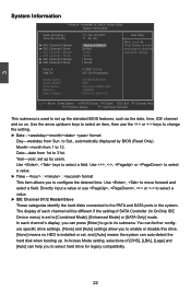
... : 49 Menu Level ► ► IDE Channel 0 Master [ Maxtor 6Y080L0 ] Press [Enter] to enter ► IDE Channel 0 Slave [None] next page for legacy compatibility. 22 to set , and [Auto] means the system can press [Enter] to go to enable or disable this drive. [None] means no HDD is used to Sat., automatically displayed by users. In Access Mode setting, selections of SATA Controller (in .] Halt On [All , But Keyboard] Model Name : G31MV/G31MV-K BIOS Version : B05 CPU Name : Genuine Intel[R] CPU Memory : 1024MB...
... : 49 Menu Level ► ► IDE Channel 0 Master [ Maxtor 6Y080L0 ] Press [Enter] to enter ► IDE Channel 0 Slave [None] next page for legacy compatibility. 22 to set , and [Auto] means the system can press [Enter] to go to enable or disable this drive. [None] means no HDD is used to Sat., automatically displayed by users. In Access Mode setting, selections of SATA Controller (in .] Halt On [All , But Keyboard] Model Name : G31MV/G31MV-K BIOS Version : B05 CPU Name : Genuine Intel[R] CPU Memory : 1024MB...
English Manual.
Page 32
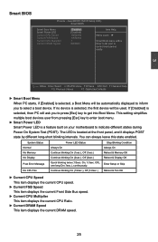
... a boot device. AwardBIOS CMOS Setup Utility Smart BIOS Smart Boot Menu [Disabled] Item Help Smart Power LED [Enabled] Current CPU Speed 1866MHz Menu Level ► Current FSB Speed 1066MHz Current CPU Multiplier 7 Smart Boot menu with a Current DRAM Speed 800MHz timer to let user to control boot device easily 3 Move Enter:Select +/-/PU/PD:Value F10:Save ESC:Exit F1:General Help F5: Previous Values F7: Optimized Defaults ► Smart Boot Menu When PC starts, if [Enabled] is located at the front panel, and it displays POST state...
... a boot device. AwardBIOS CMOS Setup Utility Smart BIOS Smart Boot Menu [Disabled] Item Help Smart Power LED [Enabled] Current CPU Speed 1866MHz Menu Level ► Current FSB Speed 1066MHz Current CPU Multiplier 7 Smart Boot menu with a Current DRAM Speed 800MHz timer to let user to control boot device easily 3 Move Enter:Select +/-/PU/PD:Value F10:Save ESC:Exit F1:General Help F5: Previous Values F7: Optimized Defaults ► Smart Boot Menu When PC starts, if [Enabled] is located at the front panel, and it displays POST state...
English Manual.
Page 35
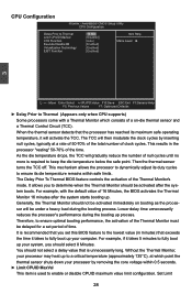
AwardBIOS CMOS Setup Utility CPU Configuration Delay Prior to Thermal Limit CPUID MaxVal C1E Function Execute Disable Bit Virtualization Technology EIST Function [16 Min] Item Help [Disabled] [Auto] Menu Level ► [Enabled] [Enabled] [Enabled] 3 Move Enter:Select +/-/PU/PD:Value F10:Save ESC:Exit F1:General Help F5: Previous Values F7: Optimized Defaults ► Delay Prior to Thermal (Appears only when CPU supports) Some processors come with the default value of time...
AwardBIOS CMOS Setup Utility CPU Configuration Delay Prior to Thermal Limit CPUID MaxVal C1E Function Execute Disable Bit Virtualization Technology EIST Function [16 Min] Item Help [Disabled] [Auto] Menu Level ► [Enabled] [Enabled] [Enabled] 3 Move Enter:Select +/-/PU/PD:Value F10:Save ESC:Exit F1:General Help F5: Previous Values F7: Optimized Defaults ► Delay Prior to Thermal (Appears only when CPU supports) Some processors come with the default value of time...
English Manual.
Page 36
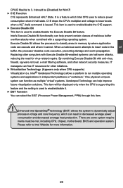
... is used to reduce power consumption when in halt state. Replacing older computers with anti-virus, firewall, spyware removal, e-mail filtering software, and other initiatives. ► Virtualization Technology (Appears only when CPU supports) Virtualization (i.e. This item will be met, including CPU, chipset, motherboard, BIOS and operation system. By combining Execute Disable Bit with Execute Disable Bit-enabled systems can select the EIST (Processor Power Management, PPM) through this feature and the setting...
... is used to reduce power consumption when in halt state. Replacing older computers with anti-virus, firewall, spyware removal, e-mail filtering software, and other initiatives. ► Virtualization Technology (Appears only when CPU supports) Virtualization (i.e. This item will be met, including CPU, chipset, motherboard, BIOS and operation system. By combining Execute Disable Bit with Execute Disable Bit-enabled systems can select the EIST (Processor Power Management, PPM) through this feature and the setting...
English Manual.
Page 37
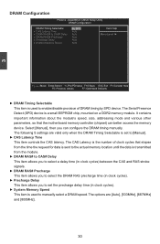
...: Optimized Defaults ► DRAM Timing Selectable This item is the number of DRAM timing by SPD device. The options are valid only when the DRAM Timing Selectable is set the precharge delay time (in clock cycles). ► System Memory Speed This item is used to enable/disable provision of clock cycles that the motherboard memory controller (chipset) can configure the DRAM timing manually. Select [Manual], then you to set to select the DRAM RAS...
...: Optimized Defaults ► DRAM Timing Selectable This item is the number of DRAM timing by SPD device. The options are valid only when the DRAM Timing Selectable is set the precharge delay time (in clock cycles). ► System Memory Speed This item is used to enable/disable provision of clock cycles that the motherboard memory controller (chipset) can configure the DRAM timing manually. Select [Manual], then you to set to select the DRAM RAS...
English Manual.
Page 38
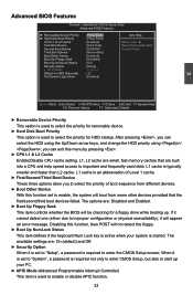
...item controls whether the BIOS will appear an error message. AwardBIOS CMOS Setup Utility Advanced BIOS Features ► Removable Device Priority ► Hard Disk Boot Priority CPU L1 & L2 Cache First Boot Device Second Boot Device Third Boot Device Boot Other Device Boot Up Floppy Seek Boot Up NumLock Status Security Option x APIC Mode Delay For HDD (Seconds) Full Screen Logo Show [Press Enter] Item Help [Press Enter] [Enabled] Menu Level ► [Hard Disk] Select Removable Boot [CDROM] Device Priorty [Removable] [Enabled] [Disabled] [On] [Setup...
...item controls whether the BIOS will appear an error message. AwardBIOS CMOS Setup Utility Advanced BIOS Features ► Removable Device Priority ► Hard Disk Boot Priority CPU L1 & L2 Cache First Boot Device Second Boot Device Third Boot Device Boot Other Device Boot Up Floppy Seek Boot Up NumLock Status Security Option x APIC Mode Delay For HDD (Seconds) Full Screen Logo Show [Press Enter] Item Help [Press Enter] [Enabled] Menu Level ► [Hard Disk] Select Removable Boot [CDROM] Device Priorty [Removable] [Enabled] [Disabled] [On] [Setup...
English Manual.
Page 40
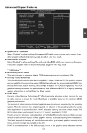
... CMOS Setup Utility Advanced Chipset Features System BIOS Cacheable [Enabled] Item Help Video BIOS Cacheable [Disabled] Menu Level ► ** VGA Setting ** PEG/Onchip VGA Control [Auto] On-Chip Frame Buffer Size 8MB DVMT Mode [DVMT] DVMT/FIXED Memory Size [128MB] Init Display First [PCI Slot] ** PCI Express Relative items ** PCI-E Compliancy Mode [v1.0a] Maximum Payload Size [128] 3 Move Enter:Select +/-/PU/PD:Value F10:Save ESC:Exit F1:General Help F5: Previous Values F7: Optimized Defaults ► System BIOS Cacheable...
... CMOS Setup Utility Advanced Chipset Features System BIOS Cacheable [Enabled] Item Help Video BIOS Cacheable [Disabled] Menu Level ► ** VGA Setting ** PEG/Onchip VGA Control [Auto] On-Chip Frame Buffer Size 8MB DVMT Mode [DVMT] DVMT/FIXED Memory Size [128MB] Init Display First [PCI Slot] ** PCI Express Relative items ** PCI-E Compliancy Mode [v1.0a] Maximum Payload Size [128] 3 Move Enter:Select +/-/PU/PD:Value F10:Save ESC:Exit F1:General Help F5: Previous Values F7: Optimized Defaults ► System BIOS Cacheable...
English Manual.
Page 41
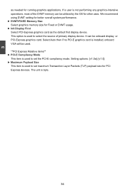
... onboard display or PCI-Express graphics card. Select Auto then if no PCI-E graphics card is installed, onboard VGA will be used. **PCI Express Relative items** ► PCI-E Compliancy Mode This item is used to set the PCI-E compliancy mode. Setting options: [v1.0a]; [v1.0]. ► Maximum Payload Size This item is not performing any graphics-intensive operations, most of primary display device. If a user is used to select the source of the DVMT memory can be utilized by the OS for PCI Express devices...
... onboard display or PCI-Express graphics card. Select Auto then if no PCI-E graphics card is installed, onboard VGA will be used. **PCI Express Relative items** ► PCI-E Compliancy Mode This item is used to set the PCI-E compliancy mode. Setting options: [v1.0a]; [v1.0]. ► Maximum Payload Size This item is not performing any graphics-intensive operations, most of primary display device. If a user is used to select the source of the DVMT memory can be utilized by the OS for PCI Express devices...
English Manual.
Page 42
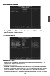
... ► OnChip IDE Devices / OnBoard Devices / SuperIO Devices / USB Devices Setting Press to go to enable DMA transfers for all IDE drives. AwardBIOS CMOS Setup Utility OnChip IDE Devices IDE HDD Block Mode [Enabled] Item Help IDE DMA Transfer Access [Enabled] On-Chip Primary PCI IDE [Enabled] Menu Level ► IDE Primary Master PIO [Auto] If your IDE hard drive supports block mode, select [Enabled] for all IDE drives. If the drive does not support DMA transfers, then it will be detected at the default [Enabled] setting. Move Enter:Select +/-/PU/PD...
... ► OnChip IDE Devices / OnBoard Devices / SuperIO Devices / USB Devices Setting Press to go to enable DMA transfers for all IDE drives. AwardBIOS CMOS Setup Utility OnChip IDE Devices IDE HDD Block Mode [Enabled] Item Help IDE DMA Transfer Access [Enabled] On-Chip Primary PCI IDE [Enabled] Menu Level ► IDE Primary Master PIO [Auto] If your IDE hard drive supports block mode, select [Enabled] for all IDE drives. If the drive does not support DMA transfers, then it will be detected at the default [Enabled] setting. Move Enter:Select +/-/PU/PD...
English Manual.
Page 44
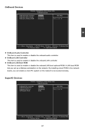
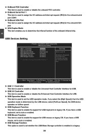
... Defaults ► OnBoard Audio Controller This item is used to enable or disable the onboard audio controller. ► OnBoard LAN Controller This item is used to enable or disable the onboard LAN controller. ► OnBoard LAN Boot ROM This item is used to be booted remotely. By installing a boot ROM in the network board, you set up a diskless workstation on the network to enable or disable the onboard LAN boot optional ROM. AwardBIOS CMOS Setup Utility SuperIO Devices OnBoard FDC Controller OnBoard Serial Port 1 OnBoard IrDA Port IrDA Duplex Mode [Enabled...
... Defaults ► OnBoard Audio Controller This item is used to enable or disable the onboard audio controller. ► OnBoard LAN Controller This item is used to enable or disable the onboard LAN controller. ► OnBoard LAN Boot ROM This item is used to be booted remotely. By installing a boot ROM in the network board, you set up a diskless workstation on the network to enable or disable the onboard LAN boot optional ROM. AwardBIOS CMOS Setup Utility SuperIO Devices OnBoard FDC Controller OnBoard Serial Port 1 OnBoard IrDA Port IrDA Duplex Mode [Enabled...
English Manual.
Page 45
AwardBIOS CMOS Setup Utility USB Devices Setting USB 1.1 Controller [Enabled] Item Help USB 2.0 Controller [Enabled] USB Operation Mode [High Speed] Menu Level ► USB Keyboard Function [Enabled] USB Mouse Function [Enabled] [Enabled] / [Disabled] USB Storage Function [Enabled] Universal Host Controller Interface *** USB Mass Storage Device Boot Setting *** for USB. ► USB Operation Mode This item is used to set to auto or enabled. ► USB Storage Function This option is used to enable the support for the onboard IrDA port. ► IrDA...
AwardBIOS CMOS Setup Utility USB Devices Setting USB 1.1 Controller [Enabled] Item Help USB 2.0 Controller [Enabled] USB Operation Mode [High Speed] Menu Level ► USB Keyboard Function [Enabled] USB Mouse Function [Enabled] [Enabled] / [Disabled] USB Storage Function [Enabled] Universal Host Controller Interface *** USB Mass Storage Device Boot Setting *** for USB. ► USB Operation Mode This item is used to set to auto or enabled. ► USB Storage Function This option is used to enable the support for the onboard IrDA port. ► IrDA...
English Manual.
Page 47
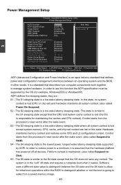
... any context. Control starts from the processor's reset vector after the wake event. (also called Suspend to use this function the ACPI specification must be supported by Ring [Enabled] Wake Up on LAN [Enabled] USB Wake Up from a saved memory image. 40 Hardware maintains memory context and restores some CPU and L2 configuration context. The S4 sleeping state is the lowest power, longest wake latency sleeping state supported by Keyboard [Disabled] KB Power On Password Enter Move Enter:Select +/-/PU...
... any context. Control starts from the processor's reset vector after the wake event. (also called Suspend to use this function the ACPI specification must be supported by Ring [Enabled] Wake Up on LAN [Enabled] USB Wake Up from a saved memory image. 40 Hardware maintains memory context and restores some CPU and L2 configuration context. The S4 sleeping state is the lowest power, longest wake latency sleeping state supported by Keyboard [Disabled] KB Power On Password Enter Move Enter:Select +/-/PU...
English Manual.
Page 48
... item is used to enable or disable the ACPI function. ► ACPI Suspend Type This item is used to set the energy saving mode of time. When you have the HPET disabled, then windows does not have access to it allows the system to resume from S3 This item is used to set the system to wake up by LAN. ► USB Wake Up from a power saving mode whenever there...
... item is used to enable or disable the ACPI function. ► ACPI Suspend Type This item is used to set the energy saving mode of time. When you have the HPET disabled, then windows does not have access to it allows the system to resume from S3 This item is used to set the system to wake up by LAN. ► USB Wake Up from a power saving mode whenever there...
English Manual.
Page 50
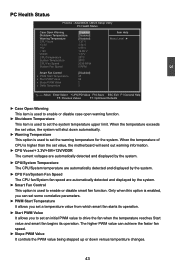
... PWM Start Temperature It allows you to set an initial PWM value to set value, the motherboard will shut down versus temperature changes. 43 AwardBIOS CMOS Setup Utility PC Health Status Case Open Warning [Disabled] Item Help Shutdown Temperature [Disabled] Warning Temperature [Disabled] Menu Level ► CPU Vcore 1.37 V +3.3V 3.34 V +5V 4.99 V +12V 12.09 V VDDR CPU Temperature System Temperature 1.77V 29oC 30oC CPU Fan Speed 2039 RPM System Fan Speed 0 RPM Smart Fan Control [Disabled] x PWM Start Temperature 35...
... PWM Start Temperature It allows you to set an initial PWM value to set value, the motherboard will shut down versus temperature changes. 43 AwardBIOS CMOS Setup Utility PC Health Status Case Open Warning [Disabled] Item Help Shutdown Temperature [Disabled] Warning Temperature [Disabled] Menu Level ► CPU Vcore 1.37 V +3.3V 3.34 V +5V 4.99 V +12V 12.09 V VDDR CPU Temperature System Temperature 1.77V 29oC 30oC CPU Fan Speed 2039 RPM System Fan Speed 0 RPM Smart Fan Control [Disabled] x PWM Start Temperature 35...
English Manual.
Page 54
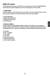
... one Utility CD. Realtek 811X LAN Driver D. FOX ONE B. Intel VGA Driver 2. Some auto features help user to install. 1. FOX LiveUpdate C. FOX DMI E. Intel Chipset Driver B. You can simply put it into your CD/DVD-ROM drive, and the main menu will be displayed on your system setting without being a computer literate. You should install the drivers in order, and you how to improve (or overclock) your system. Software Utilities Use these options to...
... one Utility CD. Realtek 811X LAN Driver D. FOX ONE B. Intel VGA Driver 2. Some auto features help user to install. 1. FOX LiveUpdate C. FOX DMI E. Intel Chipset Driver B. You can simply put it into your CD/DVD-ROM drive, and the main menu will be displayed on your system setting without being a computer literate. You should install the drivers in order, and you how to improve (or overclock) your system. Software Utilities Use these options to...


