User manual
Page 6
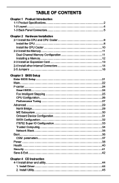
Install Driver 44 2. Table of Contents Chapter 1 Product Introduction 1-1 Product Specifications 2 1-2 Layout...4 1-3 Back Panel Connectors 5 Chapter 2 Hardware Installation 2-1 Install the CPU and CPU Cooler 8 Install the CPU 8 Install the CPU Cooler 10 2-2 Install the Memory 11 Dual Channel Memory ...
Install Driver 44 2. Table of Contents Chapter 1 Product Introduction 1-1 Product Specifications 2 1-2 Layout...4 1-3 Back Panel Connectors 5 Chapter 2 Hardware Installation 2-1 Install the CPU and CPU Cooler 8 Install the CPU 8 Install the CPU Cooler 10 2-2 Install the Memory 11 Dual Channel Memory ...

User manual
Page 8
Chapter 1 Product Introduction Thank you need for buying Foxconn B75MX Series motherboard. Foxconn products are engineered to maximize computing power, providing only what you for break-through performance. This chapter includes the following information: ■ Product Specifications ■ Layout ■ Back Panel Connectors
Chapter 1 Product Introduction Thank you need for buying Foxconn B75MX Series motherboard. Foxconn products are engineered to maximize computing power, providing only what you for break-through performance. This chapter includes the following information: ■ Product Specifications ■ Layout ■ Back Panel Connectors
User manual
Page 9
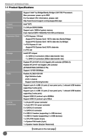
...) - 1 x SATA 3.0 connectors (6Gb/s data transfer rate) Realtek RTL8111DP-VC-CG Gigabit LAN controller (B75MX-S) Realtek RTL8111F-CG Gigabit LAN controller (B75MX/B75MX-D/B75MX-D PA) Support 10/100/1000Mbps Realtek ALC662-VD0-GR -High Definition Audio -2/4/5.1-channel -Support Jack-Sensing function ...Support up to 6 x USB 2.0 ports (2 rear panel ports, 2 onboard USB headers supporting 4 extra ports) Support up to 4 x USB 3.0 ports (2 rear panel...
...) - 1 x SATA 3.0 connectors (6Gb/s data transfer rate) Realtek RTL8111DP-VC-CG Gigabit LAN controller (B75MX-S) Realtek RTL8111F-CG Gigabit LAN controller (B75MX/B75MX-D/B75MX-D PA) Support 10/100/1000Mbps Realtek ALC662-VD0-GR -High Definition Audio -2/4/5.1-channel -Support Jack-Sensing function ...Support up to 6 x USB 2.0 ports (2 rear panel ports, 2 onboard USB headers supporting 4 extra ports) Support up to 4 x USB 3.0 ports (2 rear panel...
User manual
Page 10
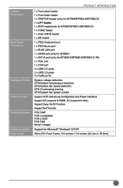
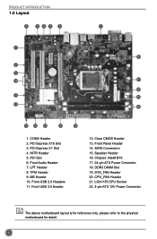
... Software Operating System Form Factor 1 x Front panel header 1 x Front Audio header 1 x TPM/TCM header (only for B75MX/B75MX-S/B75MX-D) 1 x LPT header 1 x INTR header(only for B75MX/B75MX-S/B75MX-D) 1 x COM2 header 1 x Clear CMOS header 1 x ME header 1 x PS/2 Keyboard port 1 x PS/2 Mouse port 1 x RJ45 LAN port 1 x HDMI port (only for B75MX) 1 x DVI-D port (only for B75MX-S/B75MX-D/B75MX-D PA) 1 x VGA port 1 x COM port...
... Software Operating System Form Factor 1 x Front panel header 1 x Front Audio header 1 x TPM/TCM header (only for B75MX/B75MX-S/B75MX-D) 1 x LPT header 1 x INTR header(only for B75MX/B75MX-S/B75MX-D) 1 x COM2 header 1 x Clear CMOS header 1 x ME header 1 x PS/2 Keyboard port 1 x PS/2 Mouse port 1 x RJ45 LAN port 1 x HDMI port (only for B75MX) 1 x DVI-D port (only for B75MX-S/B75MX-D/B75MX-D PA) 1 x VGA port 1 x COM port...
User manual
Page 11
.... Chipset: Intel® B75 17. 24-pin ATX Power Connector 18. SYS_FAN Header 20. INTR Header 5. Front USB 3.0 Header 12. Clear CMOS Header 13. Front Panel Header 14. LGA1155 CPU Socket 22. 4-pin ATX 12V Power Connector The above motherboard layout is for reference only, please refer to the physical motherboard...
.... Chipset: Intel® B75 17. 24-pin ATX Power Connector 18. SYS_FAN Header 20. INTR Header 5. Front USB 3.0 Header 12. Clear CMOS Header 13. Front Panel Header 14. LGA1155 CPU Socket 22. 4-pin ATX 12V Power Connector The above motherboard layout is for reference only, please refer to the physical motherboard...
User manual
Page 12
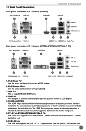
...connect external display devices, such as monitor or LCD display. 5. COM Port This is HDCP compliant. 1-3 Back Panel Connectors Back panel connectors of 5.1 channel (B75MX): PS/2 Mouse Port 1 COM Port 3 HDMI Port 5 PRODUCT INTRODUCTION LAN Port 8 Line In Line Out ...USB 3.0 Port USB 2.0 Port Audio Port Back panel connectors of 1920x1080p but the actual resolutions supported depend on the monitor being used. 5. PS/2 Keyboard Port Use the upper port to connect a PS/2 mouse. 2. DVI-D Port (B75MX-S/B75MX-D/B75MX-D PA) The DVI-D port supports DVI-D specification....
...connect external display devices, such as monitor or LCD display. 5. COM Port This is HDCP compliant. 1-3 Back Panel Connectors Back panel connectors of 5.1 channel (B75MX): PS/2 Mouse Port 1 COM Port 3 HDMI Port 5 PRODUCT INTRODUCTION LAN Port 8 Line In Line Out ...USB 3.0 Port USB 2.0 Port Audio Port Back panel connectors of 1920x1080p but the actual resolutions supported depend on the monitor being used. 5. PS/2 Keyboard Port Use the upper port to connect a PS/2 mouse. 2. DVI-D Port (B75MX-S/B75MX-D/B75MX-D PA) The DVI-D port supports DVI-D specification....
User manual
Page 20
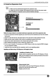
...■ Make sure the motherboard supports the expansion card. ■ Always turn off the computer and unplug the power cord from the chassis back panel. 2. Installing and Removing a PCI Express x16 Graphics Card: • Installing a Graphics Card: Gently insert the graphics card into the slot. 4.... driver provided with a screw. 5. Remove the metal slot cover from the power outlet before installing an expansion card to the chassis back panel with the expansion card in the expansion slot. 1. Turn on the card are completely inserted into the PCI Express x16 slot. Make sure...
...■ Make sure the motherboard supports the expansion card. ■ Always turn off the computer and unplug the power cord from the chassis back panel. 2. Installing and Removing a PCI Express x16 Graphics Card: • Installing a Graphics Card: Gently insert the graphics card into the slot. 4.... driver provided with a screw. 5. Remove the metal slot cover from the power outlet before installing an expansion card to the chassis back panel with the expansion card in the expansion slot. 1. Turn on the card are completely inserted into the PCI Express x16 slot. Make sure...
User manual
Page 23
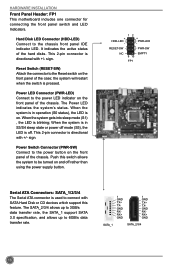
... is off rather than using the power supply button. 12 + HDD-LED - + - Power Switch Connector (PWR-SW) Connect to be turned on the front panel of the hard disks. Push this feature. The SATA_2/3/4 allows up to 3GB/s data transfer rate, the SATA_1 support SATA 3.0 specification, and allows up to... the chassis front panel IDE indicator LED. It indicates the active status of the case; When the system is in S3/S4 sleep state or power off mode (S5...
... is off rather than using the power supply button. 12 + HDD-LED - + - Power Switch Connector (PWR-SW) Connect to be turned on the front panel of the hard disks. Push this feature. The SATA_2/3/4 allows up to 3GB/s data transfer rate, the SATA_1 support SATA 3.0 specification, and allows up to... the chassis front panel IDE indicator LED. It indicates the active status of the case; When the system is in S3/S4 sleep state or power off mode (S5...
User manual
Page 32
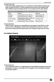
... activated, you to press [Del] key to enter setup or press [F7] key to enter smart boot menu. The LED is located at the front panel, and it displays POST state by the system, so to indicate different states during Power On Self Test (POST). Off), one long On (1sec.), continuously...
... activated, you to press [Del] key to enter setup or press [F7] key to enter smart boot menu. The LED is located at the front panel, and it displays POST state by the system, so to indicate different states during Power On Self Test (POST). Off), one long On (1sec.), continuously...
User manual
Page 54
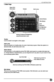
..., the alert lamp color is green. 1. Click this bar to any place on your favorite skin (FOX ONE Panel). 47 When the system is in healthy state, the color of FOX ONE screen panels. Exit FOX ONE Click here to go back to FOX ONE full screen Click here will simplify the... whole FOX ONE control panel to other pages. Simple Mode) as depicted below, you can drag this button, you monitoring system status. Switch Button Click this button, it will drop ...
..., the alert lamp color is green. 1. Click this bar to any place on your favorite skin (FOX ONE Panel). 47 When the system is in healthy state, the color of FOX ONE screen panels. Exit FOX ONE Click here to go back to FOX ONE full screen Click here will simplify the... whole FOX ONE control panel to other pages. Simple Mode) as depicted below, you can drag this button, you monitoring system status. Switch Button Click this button, it will drop ...
User manual
Page 57
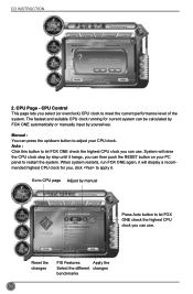
... changes FIS Features: Apply the Select the different changes benchmarks 50 CPU Page - Manual : You can press the up/down button to adjust your PC panel to restart the system. When system restarts, run FOX ONE again, it will raise the CPU clock step by yourselves. Auto : Click this button to...
... changes FIS Features: Apply the Select the different changes benchmarks 50 CPU Page - Manual : You can press the up/down button to adjust your PC panel to restart the system. When system restarts, run FOX ONE again, it will raise the CPU clock step by yourselves. Auto : Click this button to...
User manual
Page 58
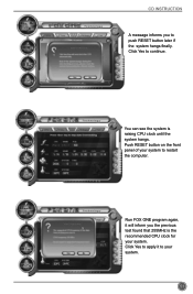
CD INSTRUCTION A message informs you the previous test found that 255MHz is raising CPU clock until the system hangs. You can see the system is the recommended CPU clock for your system to your system. 51 Run FOX ONE program again, it to restart the computer. Click Yes to push RESET button later if the system hangs finally. Push RESET button on the front panel of your system. Click Yes to apply it will inform you to continue.
CD INSTRUCTION A message informs you the previous test found that 255MHz is raising CPU clock until the system hangs. You can see the system is the recommended CPU clock for your system to your system. 51 Run FOX ONE program again, it to restart the computer. Click Yes to push RESET button later if the system hangs finally. Push RESET button on the front panel of your system. Click Yes to apply it will inform you to continue.
