
English Manual.
Page 5
... about any installation steps or have a problem related to unplug the AC power cord from the power supply outlet. Normally it comes out as a motherboard, CPU or memory. ■ Ensure that the DC power supply is a PCI Express x16 graphics card installed in your device. ■ If there is overclocked. Failure to unplug the power supply cord may result in contact with the connectors on the motherboard or within the computer casing. ■...
... about any installation steps or have a problem related to unplug the AC power cord from the power supply outlet. Normally it comes out as a motherboard, CPU or memory. ■ Ensure that the DC power supply is a PCI Express x16 graphics card installed in your device. ■ If there is overclocked. Failure to unplug the power supply cord may result in contact with the connectors on the motherboard or within the computer casing. ■...

English Manual.
Page 6
... Introduction Product Specifications 2 Layout 4 Back Panel Connectors 5 Chapter 2 Hardware Install Install the CPU and CPU Cooler 8 Install the Memory 10 Install an Expansion Card 12 Install other Internal Connectors 13 Jumpers 17 Chapter 3 BIOS Setup Enter BIOS Setup 19 Main Menu 19 System Information 21 Advanced BIOS Features 23 Fox Central Control Unit 25 Advanced Chipset Features 29 Integrated Peripherals 34 Power Management Setup 39 PC Health Status 41 BIOS Security Features 42 Load Optimal Defaults 43 Save & Exit Setup 43 Exit...
... Introduction Product Specifications 2 Layout 4 Back Panel Connectors 5 Chapter 2 Hardware Install Install the CPU and CPU Cooler 8 Install the Memory 10 Install an Expansion Card 12 Install other Internal Connectors 13 Jumpers 17 Chapter 3 BIOS Setup Enter BIOS Setup 19 Main Menu 19 System Information 21 Advanced BIOS Features 23 Fox Central Control Unit 25 Advanced Chipset Features 29 Integrated Peripherals 34 Power Management Setup 39 PC Health Status 41 BIOS Security Features 42 Load Optimal Defaults 43 Save & Exit Setup 43 Exit...
English Manual.
Page 7
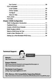
... 5 RAID Configuration RAID Configuration Introduction 71 FastBuild Driver 73 Create a RAID Driver Diskette 75 RAID Enable in BIOS 77 Select a RAID Array for Use 77 Install a New Windows XP 90 Setting Up a Non-Bootable RAID Array 94 Technical Support : Website : http://www.foxconnchannel.com Support Support Website : http://www.foxconnchannel.com/support/online.aspx or http://www.foxconnsupport.com Worldwide E-mail Support : pcebg-cisg-support@foxconn.com CPU, Memory, VGA Compatibility Supporting Website : http://www.foxconnchannel.com/product/Motherboards/compatibility...
... 5 RAID Configuration RAID Configuration Introduction 71 FastBuild Driver 73 Create a RAID Driver Diskette 75 RAID Enable in BIOS 77 Select a RAID Array for Use 77 Install a New Windows XP 90 Setting Up a Non-Bootable RAID Array 94 Technical Support : Website : http://www.foxconnchannel.com Support Support Website : http://www.foxconnchannel.com/support/online.aspx or http://www.foxconnsupport.com Worldwide E-mail Support : pcebg-cisg-support@foxconn.com CPU, Memory, VGA Compatibility Supporting Website : http://www.foxconnchannel.com/product/Motherboards/compatibility...
English Manual.
Page 9
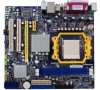
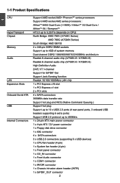
1-1 Product Specifications 1 CPU Support AMD socket AM2+ PhenomTM series processors Support AMD socket AM2 series processors : AthlonTM 64X2 Dual-Core (
1-1 Product Specifications 1 CPU Support AMD socket AM2+ PhenomTM series processors Support AMD socket AM2 series processors : AthlonTM 64X2 Dual-Core (
English Manual.
Page 10
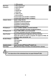
...® Windows® Vista/XP only Form Factor Micro ATX Form Factor, 9.6 inches x 8.8 inches (24.4cm x 22.4cm) ! 1 1 x TPM connector Back Panel 1 x PS/2 keyboard port Connectors 1 x PS/2 mouse port 1 x VGA port 1 x Parallel port 1 x DVI-D port 4 x USB 2.0 ports 1 x RJ-45 LAN port 8-channel Audio ports (A7VMX-S / A7GMX-S) 6-channel Audio ports (A7VMX-K / A7GMX-K) Hardware Monitor System voltage detection CPU/System temperature detection CPU/System fan speed detection CPU/System overheating warning CPU/System fan speed control PCI Express x1 Support 250MB...
...® Windows® Vista/XP only Form Factor Micro ATX Form Factor, 9.6 inches x 8.8 inches (24.4cm x 22.4cm) ! 1 1 x TPM connector Back Panel 1 x PS/2 keyboard port Connectors 1 x PS/2 mouse port 1 x VGA port 1 x Parallel port 1 x DVI-D port 4 x USB 2.0 ports 1 x RJ-45 LAN port 8-channel Audio ports (A7VMX-S / A7GMX-S) 6-channel Audio ports (A7VMX-K / A7GMX-K) Hardware Monitor System voltage detection CPU/System temperature detection CPU/System fan speed detection CPU/System overheating warning CPU/System fan speed control PCI Express x1 Support 250MB...
English Manual.
Page 14
... about CPU, Memory and VGA for your motherboard : http://www.foxconnchannel.com/product/Motherboards/compatibility.aspx Caution should be exercised during the installation of jumpers. This chapter includes the following information : ■ Install the CPU and CPU Cooler ■ Install the Memory ■ Install an Expansion Card ■ Install other Internal Connectors ■ Jumpers Please visit this chapter carefully. This chapter introduces the hardware installation process, including the installation of the CPU, memory, power supply, slots, pin headers...
... about CPU, Memory and VGA for your motherboard : http://www.foxconnchannel.com/product/Motherboards/compatibility.aspx Caution should be exercised during the installation of jumpers. This chapter includes the following information : ■ Install the CPU and CPU Cooler ■ Install the Memory ■ Install an Expansion Card ■ Install other Internal Connectors ■ Jumpers Please visit this chapter carefully. This chapter introduces the hardware installation process, including the installation of the CPU, memory, power supply, slots, pin headers...
English Manual.
Page 19
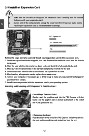
... inserted into the PCI Express x16 slot. Install the driver provided with a screw. 5. If necessary, go to BIOS Setup to release the card and then pull the card straight up from the chassis back panel. 2. Remove the metal slot cover from the slot. 12 After installing all expansion cards, replace the chassis cover. 6. 2 CAUTION 2-3 Install an Expansion Card ! ■ Make sure the motherboard supports the expansion card. Carefully read the manual that supports your expansion card(s). 7.
... inserted into the PCI Express x16 slot. Install the driver provided with a screw. 5. If necessary, go to BIOS Setup to release the card and then pull the card straight up from the chassis back panel. 2. Remove the metal slot cover from the slot. 12 After installing all expansion cards, replace the chassis cover. 6. 2 CAUTION 2-3 Install an Expansion Card ! ■ Make sure the motherboard supports the expansion card. Carefully read the manual that supports your expansion card(s). 7.
English Manual.
Page 21
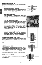
... used to connect with SATA Hard Disk or CD devices which support this switch allows the system to be turned on the front panel of the case; When the system gets into sleep mode (S1) , the LED is off. When the system is in the motherboard. Power Switch Connector (PWR-SW) Connect to the power button on the front panel of the chassis. The current Serial ATA II interface allows up to the chassis front panel IDE...
... used to connect with SATA Hard Disk or CD devices which support this switch allows the system to be turned on the front panel of the case; When the system gets into sleep mode (S1) , the LED is off. When the system is in the motherboard. Power Switch Connector (PWR-SW) Connect to the power button on the front panel of the chassis. The current Serial ATA II interface allows up to the chassis front panel IDE...
English Manual.
Page 24
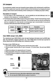
.... This will clear CMOS data. 3. For any jumper setting. The following content carefully prior to modifying any jumper on this motherboard to short them . Go to BIOS Setup to clear CMOS data are : 1. Turn off the computer, unplug the power cord from pins 2-3, put it onto pins 1-2 to modify them . Return the setting to its original with pins 2-3 closed Clear CMOS Jumper: CLR_CMOS The motherboard uses CMOS RAM to factory default when the BIOS settings were mistakenly...
.... This will clear CMOS data. 3. For any jumper setting. The following content carefully prior to modifying any jumper on this motherboard to short them . Go to BIOS Setup to clear CMOS data are : 1. Turn off the computer, unplug the power cord from pins 2-3, put it onto pins 1-2 to modify them . Return the setting to its original with pins 2-3 closed Clear CMOS Jumper: CLR_CMOS The motherboard uses CMOS RAM to factory default when the BIOS settings were mistakenly...
English Manual.
Page 32
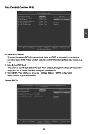
...). ► Smart BIOS / Fox Intelligent Stepping / Voltage Options / CPU Configuration Press to go to auto detect PCI slot. Smart BIOS Smart Power LED [Disabled] Help Item Smart Boot Menu Current CPU Speed [Enabled] : 2200MHz Options Current FSB/HTT Speed : 1000MHz Current DRAM Speed : 800 MHz, N/A Disabled Enabled Move Enter:Select +/-/:Value F10:Save ESC:Exit F1:General Help F9:Optimized Defaults 25 CIH. ► Auto Detect PCI Clock This option is a BIOS write-protection mechanism provided. Fox Central Control Unit CMOS Setup Utility - Copyright...
...). ► Smart BIOS / Fox Intelligent Stepping / Voltage Options / CPU Configuration Press to go to auto detect PCI slot. Smart BIOS Smart Power LED [Disabled] Help Item Smart Boot Menu Current CPU Speed [Enabled] : 2200MHz Options Current FSB/HTT Speed : 1000MHz Current DRAM Speed : 800 MHz, N/A Disabled Enabled Move Enter:Select +/-/:Value F10:Save ESC:Exit F1:General Help F9:Optimized Defaults 25 CIH. ► Auto Detect PCI Clock This option is a BIOS write-protection mechanism provided. Fox Central Control Unit CMOS Setup Utility - Copyright...

English Manual.
Page 33
... starts, it displays POST state by different long-short blinking intervals. This also prevents user without password trying to indicate different states during Power-On Self-Test (POST). Fox Intelligent Stepping CMOS Setup Utility - 3 ► Smart Power LED (Optional) Smart Power LED is a feature built on your motherboard to get into your computer through smart boot menu. ► Current CPU Speed This item displays the current CPU speed. ► Current FSB/HTT Speed This item displays the current Front Side Bus speed...
... starts, it displays POST state by different long-short blinking intervals. This also prevents user without password trying to indicate different states during Power-On Self-Test (POST). Fox Intelligent Stepping CMOS Setup Utility - 3 ► Smart Power LED (Optional) Smart Power LED is a feature built on your motherboard to get into your computer through smart boot menu. ► Current CPU Speed This item displays the current CPU speed. ► Current FSB/HTT Speed This item displays the current Front Side Bus speed...
English Manual.
Page 37
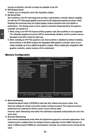
... graphics controller connected to change the clock rate of each memory bank. Enabling SurroundView does not impact display modes (resolution and color depth) or performance. When installing an ATI PCIe graphics card, SurroundView is not supported. Copyright (C) 1985-2006, American Megatrends, Inc. The integrated graphics processor (IGP) is automatically disabled, and the system memory allocated to the IGP is enabled when the installed memory capacities of SDRAM to two additional graphics outputs. Memory Configuration CMOS Setup Utility - 3 memory...
... graphics controller connected to change the clock rate of each memory bank. Enabling SurroundView does not impact display modes (resolution and color depth) or performance. When installing an ATI PCIe graphics card, SurroundView is not supported. Copyright (C) 1985-2006, American Megatrends, Inc. The integrated graphics processor (IGP) is automatically disabled, and the system memory allocated to the IGP is enabled when the installed memory capacities of SDRAM to two additional graphics outputs. Memory Configuration CMOS Setup Utility - 3 memory...
English Manual.
Page 41
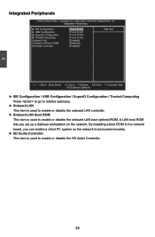
... PC system on the network. By installing a boot ROM in the network board, you set up a diskless workstation on the network to be booted remotely. ► HD Audio Controller This item is used to enable or disable the onboard LAN boot optional ROM. Copyright (C) 1985-2006, American Megatrends, Inc. Integrated Peripherals ► IDE Configuration ► USB Configuration ► SuperIO Configuration ► Trusted Computing Onboard LAN Onboard LAN Boot ROM HD Audio Controller [Press Enter] [Press Enter] [Press Enter] [Press Enter] [Enabled] [Disabled] [Enabled] Help Item...
... PC system on the network. By installing a boot ROM in the network board, you set up a diskless workstation on the network to be booted remotely. ► HD Audio Controller This item is used to enable or disable the onboard LAN boot optional ROM. Copyright (C) 1985-2006, American Megatrends, Inc. Integrated Peripherals ► IDE Configuration ► USB Configuration ► SuperIO Configuration ► Trusted Computing Onboard LAN Onboard LAN Boot ROM HD Audio Controller [Press Enter] [Press Enter] [Press Enter] [Press Enter] [Enabled] [Disabled] [Enabled] Help Item...
English Manual.
Page 42
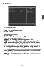
...SATA features, but some SATA drives may not support AHCI, unless they are labeled with AHCI support in its best performance. [Legacy IDE] - The Advanced Host Controller Interface (AHCI) specification describes the register level interface for a Host Controller for old Windows system . 35 This configures the SATA ports to support native IDE mode. [RAID] - OnChip SATA Type [Native IDE] Enabled: Enable the IDE controller. If your motherboard supporting AHCI, and you have a SATA device, which is used to get its specification. 3 IDE Configuration CMOS Setup Utility...
...SATA features, but some SATA drives may not support AHCI, unless they are labeled with AHCI support in its best performance. [Legacy IDE] - The Advanced Host Controller Interface (AHCI) specification describes the register level interface for a Host Controller for old Windows system . 35 This configures the SATA ports to support native IDE mode. [RAID] - OnChip SATA Type [Native IDE] Enabled: Enable the IDE controller. If your motherboard supporting AHCI, and you have a SATA device, which is used to get its specification. 3 IDE Configuration CMOS Setup Utility...
English Manual.
Page 46
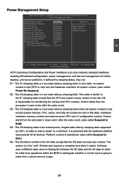
... (CPU or chip set context are : S1 - Power Management Setup ACPI Suspend Type PWRON after the wake event. (also called Suspend to the S4 state except that the CPU and system cache context is lost except system memory. The S1 sleeping state is a low wake latency sleeping state. Control starts from the processor's reset vector after PWR-Fail HPET Support Resume by LAN Resume by PCI Card Resume by PCIE Card Resume by USB Devices...
... (CPU or chip set context are : S1 - Power Management Setup ACPI Suspend Type PWRON after the wake event. (also called Suspend to the S4 state except that the CPU and system cache context is lost except system memory. The S1 sleeping state is a low wake latency sleeping state. Control starts from the processor's reset vector after PWR-Fail HPET Support Resume by LAN Resume by PCI Card Resume by PCIE Card Resume by USB Devices...
English Manual.
Page 52
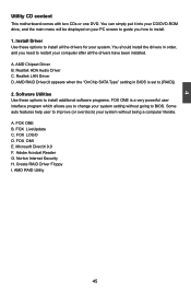
Software Utilities Use these options to change your system. FOX LiveUpdate C. Microsoft DirectX 9.0 F. AMD RAID Utility 45 Install Driver Use these options to install additional software programs. FOX ONE is set to install. 1. AMD RAID Driver(It appears when the "OnChip SATA Type" setting in order, and you how to [RAID]) 2. Create RAID Driver Floppy I. You can simply put it into your CD/DVD-ROM drive, and the main menu will be displayed on your system without going to restart your computer after...
Software Utilities Use these options to change your system. FOX LiveUpdate C. Microsoft DirectX 9.0 F. AMD RAID Utility 45 Install Driver Use these options to install additional software programs. FOX ONE is set to install. 1. AMD RAID Driver(It appears when the "OnChip SATA Type" setting in order, and you how to [RAID]) 2. Create RAID Driver Floppy I. You can simply put it into your CD/DVD-ROM drive, and the main menu will be displayed on your system without going to restart your computer after...
English Manual.
Page 77
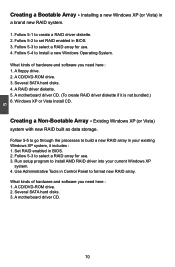
Installing a new Windows XP (or Vista) in BIOS. 3. Follow 5-2 to format new RAID array. Windows XP or Vista Install CD. Set RAID enabled in Control Panel to set RAID enabled in a brand new RAID system. 1. Use Administrative Tools in BIOS. 2. A CD/DVD-ROM drive. 2. Several SATA hard disks. 4. Existing Windows XP (or Vista) system with new RAID built as data storage. Follow 5-4 to create a RAID driver diskette. 2. Several SATA hard disks. 3. A motherboard driver CD. 70 A RAID driver diskette. 5. A motherboard driver CD. (To create RAID driver diskette if it ...
Installing a new Windows XP (or Vista) in BIOS. 3. Follow 5-2 to format new RAID array. Windows XP or Vista Install CD. Set RAID enabled in Control Panel to set RAID enabled in a brand new RAID system. 1. Use Administrative Tools in BIOS. 2. A CD/DVD-ROM drive. 2. Several SATA hard disks. 4. Existing Windows XP (or Vista) system with new RAID built as data storage. Follow 5-4 to create a RAID driver diskette. 2. Several SATA hard disks. 3. A motherboard driver CD. 70 A RAID driver diskette. 5. A motherboard driver CD. (To create RAID driver diskette if it ...
English Manual.
Page 84
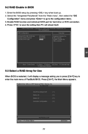
... enter the main menu of FastBuild BIOS. IDE Configuration IDE Configuration Help Item Onboard PCI IDE Controller [Enabled] Disabled: Disable the OnChip SATA Channel [Enabled] I IDE controller. Press [Ctrl-F], the Main Menu appears. Enable RAID function and individual SATA port for Use When BIOS is restarted, it will display a message asking you to press [Ctrl-F] key to save the setting then PC will reboot itself. Move Enter:Select +/-/:Value F10:Save ESC:Exit F1:General Help F9:Optimized Defaults 5-3 Select a RAID Array for hard drive or DVD connection...
... enter the main menu of FastBuild BIOS. IDE Configuration IDE Configuration Help Item Onboard PCI IDE Controller [Enabled] Disabled: Disable the OnChip SATA Channel [Enabled] I IDE controller. Press [Ctrl-F], the Main Menu appears. Enable RAID function and individual SATA port for Use When BIOS is restarted, it will display a message asking you to press [Ctrl-F] key to save the setting then PC will reboot itself. Move Enter:Select +/-/:Value F10:Save ESC:Exit F1:General Help F9:Optimized Defaults 5-3 Select a RAID Array for hard drive or DVD connection...
English Manual.
Page 98
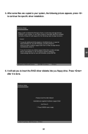
... you floppy drive. It will load support for the following picture appears, press to continue the specific driver installation. 5 5. After some files are copied to manually specify an adapter. Windows Setup Setup could not determine the type of one or more mass storage devices installed in your system, the following mass storage device(s): * To specify additional SCSI adapters, CD-ROM drivers, or special disk controllers for use with Windows, including those for use with Windows, press ENTER.
... you floppy drive. It will load support for the following picture appears, press to continue the specific driver installation. 5 5. After some files are copied to manually specify an adapter. Windows Setup Setup could not determine the type of one or more mass storage devices installed in your system, the following mass storage device(s): * To specify additional SCSI adapters, CD-ROM drivers, or special disk controllers for use with Windows, including those for use with Windows, press ENTER.
English Manual.
Page 101
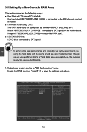
...highly recommend you using different brand of hard disks as a mirrored RAID1 array, they are : Hitachi HDT725025VLA3, (250.05GB) connected to SATA port2 of the motherboard. Enable the RAID function. IDE Configuration IDE Configuration Help Item Onboard PCI IDE Controller [Enabled] Disabled: Disable the OnChip SATA Channel [Enabled] I IDE controller. OnChip SATA Type [RAID] Enable: Enable the IDE controller. To achieve the best performance and reliability, we are configured as an example here, the purpose is connected to the IDE channel, and set...
...highly recommend you using different brand of hard disks as a mirrored RAID1 array, they are : Hitachi HDT725025VLA3, (250.05GB) connected to SATA port2 of the motherboard. Enable the RAID function. IDE Configuration IDE Configuration Help Item Onboard PCI IDE Controller [Enabled] Disabled: Disable the OnChip SATA Channel [Enabled] I IDE controller. OnChip SATA Type [RAID] Enable: Enable the IDE controller. To achieve the best performance and reliability, we are configured as an example here, the purpose is connected to the IDE channel, and set...


