
English Manual.
Page 6
...Card 12 Install other Internal Connectors 13 Jumpers 17 OnBoard Button 18 OnBoard Debug LED 18 Chapter 3 BIOS Setup Enter BIOS Setup 20 Main Menu 20 System Information 22 Advanced BIOS Features 24 Fox Central Control Unit 26 Advanced Chipset Features 31 Integrated Peripherals 39 Power Management Setup 43... PC Health Status 45 BIOS Security Features 46 Load Optimal Defaults 47 Save & Exit Setup 47 Exit Without Saving 47 Chapter 4 CD Instruction Utility CD ...
...Card 12 Install other Internal Connectors 13 Jumpers 17 OnBoard Button 18 OnBoard Debug LED 18 Chapter 3 BIOS Setup Enter BIOS Setup 20 Main Menu 20 System Information 22 Advanced BIOS Features 24 Fox Central Control Unit 26 Advanced Chipset Features 31 Integrated Peripherals 39 Power Management Setup 43... PC Health Status 45 BIOS Security Features 46 Load Optimal Defaults 47 Save & Exit Setup 47 Exit Without Saving 47 Chapter 4 CD Instruction Utility CD ...

English Manual.
Page 7
... FOX LOGO 71 FOX DMI 72 Chapter 5 RAID Configuration RAID Configuration Introduction 75 Option ROM Utility 77 Create a RAID Driver Diskette 79 RAID Enable in BIOS 81 Select a RAID Array for Use 81 Install a New Windows XP 96 Setting Up a Non-Bootable RAID Array 100 Appendix -
... FOX LOGO 71 FOX DMI 72 Chapter 5 RAID Configuration RAID Configuration Introduction 75 Option ROM Utility 77 Create a RAID Driver Diskette 79 RAID Enable in BIOS 81 Select a RAID Array for Use 81 Install a New Windows XP 96 Setting Up a Non-Bootable RAID Array 100 Appendix -
English Manual.
Page 17
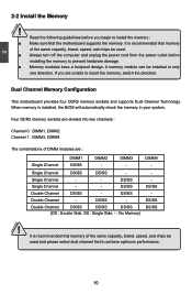
... : Double Side, SS : Single Side, - : No Memory) DS/SS DS/SS DS/SS ! CAUTION 10 DS/SS Double Channel DS/SS - It is installed, the BIOS will automatically check the memory in only one direction. DIMM4 -
... : Double Side, SS : Single Side, - : No Memory) DS/SS DS/SS DS/SS ! CAUTION 10 DS/SS Double Channel DS/SS - It is installed, the BIOS will automatically check the memory in only one direction. DIMM4 -

English Manual.
Page 19
... off the computer and unplug the power cord from the power outlet before installing an expansion card to make any required BIOS changes for your card. If necessary, go to BIOS Setup to prevent hardware damage. Installing and Removing a PCI Express x16 Graphics Card : • Installing a Graphics Card: Gently insert the graphics...
... off the computer and unplug the power cord from the power outlet before installing an expansion card to make any required BIOS changes for your card. If necessary, go to BIOS Setup to prevent hardware damage. Installing and Removing a PCI Express x16 Graphics Card : • Installing a Graphics Card: Gently insert the graphics...

English Manual.
Page 23
... for S/PDIF output. These fans can be controlled and monitored in "PC Health Status" section of this motherboard. By connecting through the function of the BIOS Setup. The fan speed can be connected to a security switch on the front panel. 12 VCC DD+ GND EMPTY VCC DD+ GND NC 9 10 F_USB...
... for S/PDIF output. These fans can be controlled and monitored in "PC Health Status" section of this motherboard. By connecting through the function of the BIOS Setup. The fan speed can be connected to a security switch on the front panel. 12 VCC DD+ GND EMPTY VCC DD+ GND NC 9 10 F_USB...

English Manual.
Page 24
...also be identified by a screwdriver for a few seconds, but using jumper cap is turned on the two pins to factory default when the BIOS settings were mistakenly modified. Turn off the computer, unplug the power cord from pins 2 and 3, put it onto pins 1 and 2 ...means placing a jumper cap on . 17 Description of the jumper settings. This section explains how to store the basic hardware information (such as BIOS data, date, time information, hardware password...etc.). Users should read the following table explains different types of Jumpers 1. For any jumper setting....
...also be identified by a screwdriver for a few seconds, but using jumper cap is turned on the two pins to factory default when the BIOS settings were mistakenly modified. Turn off the computer, unplug the power cord from pins 2 and 3, put it onto pins 1 and 2 ...means placing a jumper cap on . 17 Description of the jumper settings. This section explains how to store the basic hardware information (such as BIOS data, date, time information, hardware password...etc.). Users should read the following table explains different types of Jumpers 1. For any jumper setting....

English Manual.
Page 26
... for reference only. You want to run the Setup Program when the following information : ■ Enter BIOS Setup ■ Main Menu ■ System Information ■ Advanced BIOS Features ■ Fox Central Control Unit ■ Advanced Chipset Features ■ Integrated Peripherals ■ Power... Management Setup ■ PC Health Status ■ BIOS Security Features ■ Load Optimial Defaults ■ Save & Exit Setup ■ Exit Without Saving Since BIOS could be updated some other times, the BIOS information described in the future. Detailed descriptions of this manual ...
... for reference only. You want to run the Setup Program when the following information : ■ Enter BIOS Setup ■ Main Menu ■ System Information ■ Advanced BIOS Features ■ Fox Central Control Unit ■ Advanced Chipset Features ■ Integrated Peripherals ■ Power... Management Setup ■ PC Health Status ■ BIOS Security Features ■ Load Optimial Defaults ■ Save & Exit Setup ■ Exit Without Saving Since BIOS could be updated some other times, the BIOS information described in the future. Detailed descriptions of this manual ...

English Manual.
Page 27
... SETUP. ! Copyright (C) 1985-2005, American Megatrends, Inc. ► System Information ► PC Health Status ► Advanced BIOS Features ► BIOS Security Features ► Fox Central Control Unit Load Optimal Defaults ► Advanced Chipset Features Save & Exit Setup ► Integrated Peripherals...9658; System Information It displays the basic system configuration, such as Serial I/O and other USB devices... Each item in the BIOS Setup, and we shall not be responsible for the chipset can be changed through this menu, and the system performance can ...
... SETUP. ! Copyright (C) 1985-2005, American Megatrends, Inc. ► System Information ► PC Health Status ► Advanced BIOS Features ► BIOS Security Features ► Fox Central Control Unit Load Optimal Defaults ► Advanced Chipset Features Save & Exit Setup ► Integrated Peripherals...9658; System Information It displays the basic system configuration, such as Serial I/O and other USB devices... Each item in the BIOS Setup, and we shall not be responsible for the chipset can be changed through this menu, and the system performance can ...

English Manual.
Page 28
... setting values to CMOS and exit. ► Exit Without Saving Do not change Fan speeds, and displays temperatures and voltages of your CPU/System. ► BIOS Security Features The Supervisor/User password can be loaded through this menu. If you set a password, the system will ask you to key in some... ways (such as less I /O cards installed. However, it may sometimes come out an unstable system. What you need now is to adjust BIOS setting one by one, trial and error, to find out the best setting for your system loading is heavy, set to optimal default may cause...
... setting values to CMOS and exit. ► Exit Without Saving Do not change Fan speeds, and displays temperatures and voltages of your CPU/System. ► BIOS Security Features The Supervisor/User password can be loaded through this menu. If you set a password, the system will ask you to key in some... ways (such as less I /O cards installed. However, it may sometimes come out an unstable system. What you need now is to adjust BIOS setting one by one, trial and error, to find out the best setting for your system loading is heavy, set to optimal default may cause...

English Manual.
Page 29
..., Inc. to Sat., this message is used to move forward a field. The three fields of the Floppy Disk Drive is detected during powering up by BIOS (Read Only). It can be [360KB, 51/4"], [1.2MB, 51/4"], [720KB, 31/2"], [1.44MB, 31/2"], [2.88 MB, 31/2"] and [Disabled]. ► Halt On ... [TAB] or [SHIFT-TAB] to input the value. ► Primary/Secondary/Third/Fourth IDE Master/Slave,Fifth/Sixth IDE Master While entering setup, BIOS automatically detects the presence of IDE devices. The halt condition can be enabled/disabled in your system. Use the arrow up/down keys to select...
..., Inc. to Sat., this message is used to move forward a field. The three fields of the Floppy Disk Drive is detected during powering up by BIOS (Read Only). It can be [360KB, 51/4"], [1.2MB, 51/4"], [720KB, 31/2"], [1.44MB, 31/2"], [2.88 MB, 31/2"] and [Disabled]. ► Halt On ... [TAB] or [SHIFT-TAB] to input the value. ► Primary/Secondary/Third/Fourth IDE Master/Slave,Fifth/Sixth IDE Master While entering setup, BIOS automatically detects the presence of IDE devices. The halt condition can be enabled/disabled in your system. Use the arrow up/down keys to select...
English Manual.
Page 30
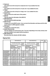
...this item. ► Model Name This item shows the model name of this information and discuss with the field service people if a BIOS upgrade is depending on how many memory modules were installed in your system before powering on. ► MAC Address1/2 This item shows ... Size This item displays the current memory size. User can check this product. ► BIOS ID This item shows the information of the BIOS ID. ► BIOS Build Date This item shows the BIOS build date. ► BIOS Version It displays the current BIOS version. ESATA2 23 ESATA2 ESATA2 ESATA2 - - ESATA1 -
...this item. ► Model Name This item shows the model name of this information and discuss with the field service people if a BIOS upgrade is depending on how many memory modules were installed in your system before powering on. ► MAC Address1/2 This item shows ... Size This item displays the current memory size. User can check this product. ► BIOS ID This item shows the information of the BIOS ID. ► BIOS Build Date This item shows the BIOS build date. ► BIOS Version It displays the current BIOS version. ESATA2 23 ESATA2 ESATA2 ESATA2 - - ESATA1 -

English Manual.
Page 31
... can conduct their transactions for a longer time. Normally, a default value of 64 cycles is in unit of POST messages. 24 Advanced BIOS Features MPS Revision PCI Latency Timer Quiet Boot Quick Boot Bootup Num-Lock Floppy Drive Seek [1.4] Help Item [64] [Enabled] Select the... access, they can retain control of the MPS that doesn't come with a PCI bridge. Copyright (C) 1985-2005, American Megatrends, Inc. Advanced BIOS Features CMOS Setup Utility - Setting values are running an older operating system that only supports MPS 1.1. ► PCI Latency Timer This item is...
... can conduct their transactions for a longer time. Normally, a default value of 64 cycles is in unit of POST messages. 24 Advanced BIOS Features MPS Revision PCI Latency Timer Quiet Boot Quick Boot Bootup Num-Lock Floppy Drive Seek [1.4] Help Item [64] [Enabled] Select the... access, they can retain control of the MPS that doesn't come with a PCI bridge. Copyright (C) 1985-2005, American Megatrends, Inc. Advanced BIOS Features CMOS Setup Utility - Setting values are running an older operating system that only supports MPS 1.1. ► PCI Latency Timer This item is...

English Manual.
Page 32
... This item defines if the keyboard Num Lock key is active when your system is started. 3 ► Quick Boot While Enabled, this option allows BIOS to skip certain tests while booting, this function, then POST will not detect the floppy. 25 The available settings are: On (default) and Off.... ► Floppy Drive Seek This item controls whether the BIOS will appear an error message. If it cannot detect one (either due to improper configuration or physical unavailability), it will be checking for a floppy ...
... This item defines if the keyboard Num Lock key is active when your system is started. 3 ► Quick Boot While Enabled, this option allows BIOS to skip certain tests while booting, this function, then POST will not detect the floppy. 25 The available settings are: On (default) and Off.... ► Floppy Drive Seek This item controls whether the BIOS will appear an error message. If it cannot detect one (either due to improper configuration or physical unavailability), it will be checking for a floppy ...

English Manual.
Page 33
...performance. Fox Central Control Unit CMOS Setup Utility - Copyright (C) 1985-2005, American Megatrends, Inc. Fox Central Control Unit ► Smart BIOS ► Fox Intelligent Stepping ► Voltage Configuration ► CPU Configuration Advanced Clock Calibration [Press Enter] [Press Enter] [Press Enter] ...American Megatrends, Inc. Select [All Cores], all cores will automatically determine to select the calibration mode for every core. ! Smart BIOS Smart Power LED [Disabled] Help Item Smart Boot Menu [Enabled] Current CPU Speed : 2700MHz Options Current FSB/HTT Speed :...
...performance. Fox Central Control Unit CMOS Setup Utility - Copyright (C) 1985-2005, American Megatrends, Inc. Fox Central Control Unit ► Smart BIOS ► Fox Intelligent Stepping ► Voltage Configuration ► CPU Configuration Advanced Clock Calibration [Press Enter] [Press Enter] [Press Enter] ...American Megatrends, Inc. Select [All Cores], all cores will automatically determine to select the calibration mode for every core. ! Smart BIOS Smart Power LED [Disabled] Help Item Smart Boot Menu [Enabled] Current CPU Speed : 2700MHz Options Current FSB/HTT Speed :...
English Manual.
Page 38
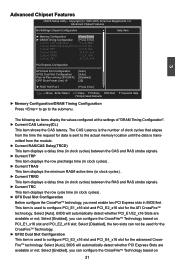
... and PCI_E4_x16 slot for the ATI CrossFireTM technology. Select [Enabled], you can configure the CrossFireTM Technology based on 31 Select [Auto], BIOS will automatically detect whether PCI_E1/E2_x16 Slots are available or not; This item is the number of "DRAM Timing Configuration". ►...(in clock cycles) . ► GFX Dual Slot Configuration Before configure the CrossFireTM technology, you need enable two PCI Express slots in BIOS first. Advanced Chipset Features CMOS Setup Utility - Select [Enabled], you can not be used for the CrossFireTM Technology. ► GFX2 Dual...
... and PCI_E4_x16 slot for the ATI CrossFireTM technology. Select [Enabled], you can configure the CrossFireTM Technology based on 31 Select [Auto], BIOS will automatically detect whether PCI_E1/E2_x16 Slots are available or not; This item is the number of "DRAM Timing Configuration". ►...(in clock cycles) . ► GFX Dual Slot Configuration Before configure the CrossFireTM technology, you need enable two PCI Express slots in BIOS first. Advanced Chipset Features CMOS Setup Utility - Select [Enabled], you can not be used for the CrossFireTM Technology. ► GFX2 Dual...
English Manual.
Page 40
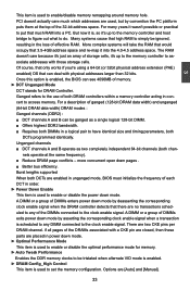
... of effective RAM. if all pages of the DRAMs associated with a CKE pin are closed, then these parts are enabled in unganged mode, BIOS must initialize the frequency of each DCT in power down mode by convention the PC platform puts them at the same frequency). ■ Reduce ... : Ganged channels (DDR2) : ■ DCT channels A and B can see 4096MB of DIMMs enters power down mode. Once this option is enabled, the BIOS can be ignored, resulting in a logical pair to have identical size and timing parameters, both DRAM controllers within a memory controller acting in concert to access...
... of effective RAM. if all pages of the DRAMs associated with a CKE pin are closed, then these parts are enabled in unganged mode, BIOS must initialize the frequency of each DCT in power down mode by convention the PC platform puts them at the same frequency). ■ Reduce ... : Ganged channels (DDR2) : ■ DCT channels A and B can see 4096MB of DIMMs enters power down mode. Once this option is enabled, the BIOS can be ignored, resulting in a logical pair to have identical size and timing parameters, both DRAM controllers within a memory controller acting in concert to access...
English Manual.
Page 41
For example, if this field, BIOS must convert the tFAW parameter into MEMCLK cycles by the lowest period (highest frequency) of times that the oldest memory-access request in the DRAM ...
For example, if this field, BIOS must convert the tFAW parameter into MEMCLK cycles by the lowest period (highest frequency) of times that the oldest memory-access request in the DRAM ...
English Manual.
Page 42
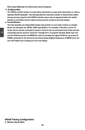
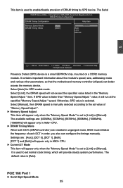
..., mounted on a DDR2 memory module. The available settings are: [400MHz], [533MHz], [667MHz], [800MHz], [1066MHz]. [1066MHz] will not exceed the specified value listed in unganged mode, BIOS must initialize the frequency of "Memory Speed Adjust ". ► Memory Speed Adjust This item will provide steady system performance. The default value is selected. Otherwise...
..., mounted on a DDR2 memory module. The available settings are: [400MHz], [533MHz], [667MHz], [800MHz], [1066MHz]. [1066MHz] will not exceed the specified value listed in unganged mode, BIOS must initialize the frequency of "Memory Speed Adjust ". ► Memory Speed Adjust This item will provide steady system performance. The default value is selected. Otherwise...
English Manual.
Page 43
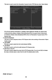
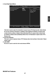
... Mode [Auto] Help Item Gen2 De-Emphasis [-3.5dB] Link ASPM [Disabled] "Auto" - Select [Software Initiated], the speed mode is determined by software initiated; Select [Disabled], BIOS will only advertize Generation II capability; Move Enter:Select +/-/:Value F10:Save ESC:Exit F1:General Help F9:Optimized Defaults RC will turn off Generation...
... Mode [Auto] Help Item Gen2 De-Emphasis [-3.5dB] Link ASPM [Disabled] "Auto" - Select [Software Initiated], the speed mode is determined by software initiated; Select [Disabled], BIOS will only advertize Generation II capability; Move Enter:Select +/-/:Value F10:Save ESC:Exit F1:General Help F9:Optimized Defaults RC will turn off Generation...
English Manual.
Page 44
... speed mode of PCI Express slots when working in Generation II Specification mode. ► Link ASPM This item is determined by software initiated; Select [Disabled], BIOS will only advertize Generation II capability; RC only advertize Gen2 capability. Select [Auto], RC will turn off Generation II speed mode of PCI Express slots...
... speed mode of PCI Express slots when working in Generation II Specification mode. ► Link ASPM This item is determined by software initiated; Select [Disabled], BIOS will only advertize Generation II capability; RC only advertize Gen2 capability. Select [Auto], RC will turn off Generation II speed mode of PCI Express slots...


