English Manual.
Page 5
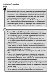
... high-quality, certified fans in order to avoid damage to the motherboard and CPU due to the internal connectors on the computer if the CPU fan is not properly installed. ■ We cannot guarantee that the DC power supply is a PCI Express x16 graphics card installed in contact with the connectors on the motherboard. Incorrect connections might damage the motherboard. ■ When handling the motherboard, avoid touching any installation steps or have a problem...
... high-quality, certified fans in order to avoid damage to the motherboard and CPU due to the internal connectors on the computer if the CPU fan is not properly installed. ■ We cannot guarantee that the DC power supply is a PCI Express x16 graphics card installed in contact with the connectors on the motherboard. Incorrect connections might damage the motherboard. ■ When handling the motherboard, avoid touching any installation steps or have a problem...

English Manual.
Page 6
... Introduction Product Specifications 2 Layout...4 Back Panel Connectors 5 Chapter 2 Hardware Install Install the CPU and CPU Cooler 8 Install the Memory 10 Install an Expansion Card 12 Install other Internal Connectors 13 Jumpers 17 OnBoard Button 18 OnBoard Debug LED 18 Chapter 3 BIOS Setup Enter BIOS Setup 20 Main Menu 20 System Information 22 Advanced BIOS Features 24 Fox Central Control Unit 26 Advanced Chipset Features 31 Integrated Peripherals 39 Power Management Setup 43 PC Health Status 45 BIOS Security Features 46 Load Optimal Defaults 47 Save...
... Introduction Product Specifications 2 Layout...4 Back Panel Connectors 5 Chapter 2 Hardware Install Install the CPU and CPU Cooler 8 Install the Memory 10 Install an Expansion Card 12 Install other Internal Connectors 13 Jumpers 17 OnBoard Button 18 OnBoard Debug LED 18 Chapter 3 BIOS Setup Enter BIOS Setup 20 Main Menu 20 System Information 22 Advanced BIOS Features 24 Fox Central Control Unit 26 Advanced Chipset Features 31 Integrated Peripherals 39 Power Management Setup 43 PC Health Status 45 BIOS Security Features 46 Load Optimal Defaults 47 Save...

English Manual.
Page 7
... contact Support : http://www.foxconnchannel.com/support/online.aspx CPU, Memory, VGA Compatibility Supporting Website : http://www.foxconnchannel.com/product/Motherboards/compatibility.aspx FOX LiveUpdate Local Update 63 Online Update 65 Configure 68 About & Help 70 FOX LOGO 71 FOX DMI 72 Chapter 5 RAID Configuration RAID Configuration Introduction 75 Option ROM Utility 77 Create a RAID Driver Diskette 79 RAID Enable in BIOS 81 Select a RAID Array for Use 81 Install a New Windows XP 96 Setting Up a Non-Bootable RAID Array...
... contact Support : http://www.foxconnchannel.com/support/online.aspx CPU, Memory, VGA Compatibility Supporting Website : http://www.foxconnchannel.com/product/Motherboards/compatibility.aspx FOX LiveUpdate Local Update 63 Online Update 65 Configure 68 About & Help 70 FOX LOGO 71 FOX DMI 72 Chapter 5 RAID Configuration RAID Configuration Introduction 75 Option ROM Utility 77 Create a RAID Driver Diskette 79 RAID Enable in BIOS 81 Select a RAID Array for Use 81 Install a New Windows XP 96 Setting Up a Non-Bootable RAID Array...
English Manual.
Page 10
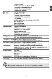
... 1 x 24-pin ATX main power connector 1 x 8-pin ATX 12V power connector 1 x AUX Power connector Back Panel 1 x PS/2 keyboard port Connectors 1 x PS/2 mouse port 1 x Optical S/PDIF out connector 1 x Coaxial S/PDIF out connector 1 x 1394a port 2 x External SATA ports (Controlled by Jmicron 362) 6 x USB 2.0 ports 2 x RJ-45 LAN ports 8-channel Audio ports Hardware Monitor System voltage detection CPU/System temperature detection CPU/System fan speed detection System voltage warning CPU/System overheating warning CPU/System fan speed control PCI Express x1 Support 250MB...
... 1 x 24-pin ATX main power connector 1 x 8-pin ATX 12V power connector 1 x AUX Power connector Back Panel 1 x PS/2 keyboard port Connectors 1 x PS/2 mouse port 1 x Optical S/PDIF out connector 1 x Coaxial S/PDIF out connector 1 x 1394a port 2 x External SATA ports (Controlled by Jmicron 362) 6 x USB 2.0 ports 2 x RJ-45 LAN ports 8-channel Audio ports Hardware Monitor System voltage detection CPU/System temperature detection CPU/System fan speed detection System voltage warning CPU/System overheating warning CPU/System fan speed control PCI Express x1 Support 250MB...

English Manual.
Page 14
... CPU, memory, power supply, slots, pin headers and the mounting of these modules. Please refer to the motherboard layout prior to any installation and read the contents in this website for more supporting information about CPU, Memory and VGA for your motherboard : http://www.foxconnchannel.com/product/Motherboards/compatibility.aspx This chapter includes the following information : ■ Install the CPU and CPU Cooler ■ Install the Memory ■ Install an Expansion Card ■ Install other Internal Connectors...
... CPU, memory, power supply, slots, pin headers and the mounting of these modules. Please refer to the motherboard layout prior to any installation and read the contents in this website for more supporting information about CPU, Memory and VGA for your motherboard : http://www.foxconnchannel.com/product/Motherboards/compatibility.aspx This chapter includes the following information : ■ Install the CPU and CPU Cooler ■ Install the Memory ■ Install an Expansion Card ■ Install other Internal Connectors...

English Manual.
Page 19
... completely inserted into the PCI Express x16 slot. Secure the card's metal bracket to make any required BIOS changes for your expansion card. ■ Always turn off the computer and unplug the power cord from the chassis back panel. 2. 2 CAUTION 2-3 Install an Expansion Card ! ■ Make sure the motherboard supports the expansion card. Remove the metal slot cover from the power outlet before installing an expansion card to prevent hardware damage...
... completely inserted into the PCI Express x16 slot. Secure the card's metal bracket to make any required BIOS changes for your expansion card. ■ Always turn off the computer and unplug the power cord from the chassis back panel. 2. 2 CAUTION 2-3 Install an Expansion Card ! ■ Make sure the motherboard supports the expansion card. Remove the metal slot cover from the power outlet before installing an expansion card to prevent hardware damage...

English Manual.
Page 22
... motherboard supports one connector for legacy compatibility. When the system gets into sleep mode (S1) , the LED is pressed. Power Switch Connector (PWR-SW) Connect to the Reset switch on the front panel of the chassis. Hard Disk LED Connector (HDD-LED) Connect to 300MB/s data transfer rate. 12 + + HDD-LED - Reset Switch (RESET-SW) Attach the connector to the power button on the front panel of the case; the system will restart when the switch is blinking; This 2-pin connector is used to any IDE type of the hard disks...
... motherboard supports one connector for legacy compatibility. When the system gets into sleep mode (S1) , the LED is pressed. Power Switch Connector (PWR-SW) Connect to the Reset switch on the front panel of the chassis. Hard Disk LED Connector (HDD-LED) Connect to 300MB/s data transfer rate. 12 + + HDD-LED - Reset Switch (RESET-SW) Attach the connector to the power button on the front panel of the case; the system will restart when the switch is blinking; This 2-pin connector is used to any IDE type of the hard disks...

English Manual.
Page 24
... motherboard, pin 1 can also be identified by changing the jumper settings. Go to BIOS Setup to configure new system as described in this manual, pin 1 is turned on this motherboard by the bold silkscreen next to short them . Normal 1 2 (Default) 3 CLR_CMOS ■ Disconnect the power cable before adjusting the jumper settings. ■ Do not clear the CMOS while the system is simply labeled as BIOS data, date, time information, hardware password...etc.). Plug...
... motherboard, pin 1 can also be identified by changing the jumper settings. Go to BIOS Setup to configure new system as described in this manual, pin 1 is turned on this motherboard by the bold silkscreen next to short them . Normal 1 2 (Default) 3 CLR_CMOS ■ Disconnect the power cable before adjusting the jumper settings. ■ Do not clear the CMOS while the system is simply labeled as BIOS data, date, time information, hardware password...etc.). Plug...

English Manual.
Page 31
... used to set . Advanced BIOS Features MPS Revision PCI Latency Timer Quiet Boot Quick Boot Bootup Num-Lock Floppy Drive Seek [1.4] Help Item [64] [Enabled] Select the time out [Enabled] value for PCI device latency timer register. This feature controls how long each PCI device to the disadvantage of other devices on a motherboard that only supports MPS 1.1. ► PCI Latency Timer This item is used to enable/disable the quiet boot. [Disabled] : Displays the normal POST messages. [Enabled] : Displays...
... used to set . Advanced BIOS Features MPS Revision PCI Latency Timer Quiet Boot Quick Boot Bootup Num-Lock Floppy Drive Seek [1.4] Help Item [64] [Enabled] Select the time out [Enabled] value for PCI device latency timer register. This feature controls how long each PCI device to the disadvantage of other devices on a motherboard that only supports MPS 1.1. ► PCI Latency Timer This item is used to enable/disable the quiet boot. [Disabled] : Displays the normal POST messages. [Enabled] : Displays...

English Manual.
Page 34
... front panel, and it displays POST state by different long-short blinking intervals. Please refer to control boot device easily. ► Current CPU Speed This item displays the current CPU speed. ► Current FSB/HTT Speed This item displays the current Front Side Bus speed. ► Current CPU Multiplier This item displays the current CPU Ratio. ► Current Memory Speed This item displays the current memory speed. 3 ► Smart Power LED Smart Power LED is used to enable or disable the smart boot menu. Enter Setup or Skip No CPU Fan...
... front panel, and it displays POST state by different long-short blinking intervals. Please refer to control boot device easily. ► Current CPU Speed This item displays the current CPU speed. ► Current FSB/HTT Speed This item displays the current Front Side Bus speed. ► Current CPU Multiplier This item displays the current CPU Ratio. ► Current Memory Speed This item displays the current memory speed. 3 ► Smart Power LED Smart Power LED is used to enable or disable the smart boot menu. Enter Setup or Skip No CPU Fan...
English Manual.
Page 39
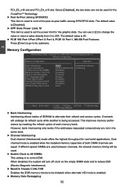
The default value is [Disabled]. ► GPP Slots Power Limit, W This item is 25. ► PCIE 16X Port 1/Port 2/Port 3/ Port 4, PCIE 1X Port 1, NB-SB Port Features Press [Enter] to go to its refresh cycle while another is used for the CrossFireTM Technology. ► Peer-to ALL DIMMs [Disabled] MemClk Tristate C3/ALTVID [Disabled] Memory Hole Remapping [Enabled] DCT Unganged Mode [Always] Power Down Enable [Disabled] Optimal Performance Mode [Disabled] Auto Tweak Performance [Disabled] DRAM Config_High Control [Auto] Move Enter:Select...
The default value is [Disabled]. ► GPP Slots Power Limit, W This item is 25. ► PCIE 16X Port 1/Port 2/Port 3/ Port 4, PCIE 1X Port 1, NB-SB Port Features Press [Enter] to go to its refresh cycle while another is used for the CrossFireTM Technology. ► Peer-to ALL DIMMs [Disabled] MemClk Tristate C3/ALTVID [Disabled] Memory Hole Remapping [Enabled] DCT Unganged Mode [Always] Power Down Enable [Disabled] Optimal Performance Mode [Disabled] Auto Tweak Performance [Disabled] DRAM Config_High Control [Auto] Move Enter:Select...
English Manual.
Page 40
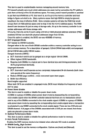
... used to enable/disable memory remapping around memory hole. Once this option is used , but by deasserting the corresponding clock enable signal when the DRAM controller detects that much which addresses are [Auto] and [Manual]. 33 Many systems cause that can see 4096MB of the 32-bit address space. There are no transactions scheduled to any DIMM connected to simply be ignored, resulting in power down mode...
... used to enable/disable memory remapping around memory hole. Once this option is used , but by deasserting the corresponding clock enable signal when the DRAM controller detects that much which addresses are [Auto] and [Manual]. 33 Many systems cause that can see 4096MB of the 32-bit address space. There are no transactions scheduled to any DIMM connected to simply be ignored, resulting in power down mode...

English Manual.
Page 46
By installing a boot ROM in the network board, you set up a diskless workstation on the network to be booted remotely. ► IEEE1394 This item is used to enable or disable the IEEE1394 function. ► HD Audio Controller This item is used to enable or disable the onboard LAN boot optional ROM. Copyright (C) 1985-2005, American Megatrends, Inc. Integrated Peripherals ► IDE Configuration ► USB Configuration ► SuperIO Configuration OnBoard LAN OnBoard LAN Boot ROM IEEE1394 HD Audio Controller [Press Enter] Help Item [Press Enter] [Press Enter] Configure the IDE...
By installing a boot ROM in the network board, you set up a diskless workstation on the network to be booted remotely. ► IEEE1394 This item is used to enable or disable the IEEE1394 function. ► HD Audio Controller This item is used to enable or disable the onboard LAN boot optional ROM. Copyright (C) 1985-2005, American Megatrends, Inc. Integrated Peripherals ► IDE Configuration ► USB Configuration ► SuperIO Configuration OnBoard LAN OnBoard LAN Boot ROM IEEE1394 HD Audio Controller [Press Enter] Help Item [Press Enter] [Press Enter] Configure the IDE...
English Manual.
Page 47
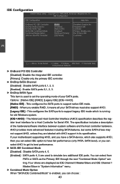
...the primary IDE controller. ► OnChip SATA Channel [Disabled] : Disable SATA ports 0,1, 2, 3. [Enabled] : Enable SATA ports 0,1, 2, 3. ► OnChip SATA Type This item is enabled, you enable RAID, it means all your SATA ports. Four drives are used to support native IDE mode. [RAID] - IDE Configuration CMOS Setup Utility - SATA IDE Combined Mode [Enabled] Primary: Enable only Combined Mode Option [SATA as the Primary IDE through the next "Combined Mode Option" setting. The specification includes a description of your SATA drives must also support AHCI. [Legacy IDE] -
...the primary IDE controller. ► OnChip SATA Channel [Disabled] : Disable SATA ports 0,1, 2, 3. [Enabled] : Enable SATA ports 0,1, 2, 3. ► OnChip SATA Type This item is enabled, you enable RAID, it means all your SATA ports. Four drives are used to support native IDE mode. [RAID] - IDE Configuration CMOS Setup Utility - SATA IDE Combined Mode [Enabled] Primary: Enable only Combined Mode Option [SATA as the Primary IDE through the next "Combined Mode Option" setting. The specification includes a description of your SATA drives must also support AHCI. [Legacy IDE] -

English Manual.
Page 48
... ESATA ports on legacy OS. Setting values are Legacy USB Support [Enabled] connected. This item is a workaround for EHCI BIOS handoff will be used to boot as hard drive. [Forced FDD] option can be available in charge of this USB device, such as [Auto], [Floppy], [Forced FDD], [Hard Disk] and [CDROM] can set the transmission rate mode of features in the Enhanced Host Controller Interface (EHCI) specification, but there are a few features that are : [High Speed...
... ESATA ports on legacy OS. Setting values are Legacy USB Support [Enabled] connected. This item is a workaround for EHCI BIOS handoff will be used to boot as hard drive. [Forced FDD] option can be available in charge of this USB device, such as [Auto], [Floppy], [Forced FDD], [Hard Disk] and [CDROM] can set the transmission rate mode of features in the Enhanced Host Controller Interface (EHCI) specification, but there are a few features that are : [High Speed...
English Manual.
Page 52
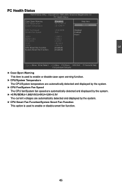
...; CPU/System Temperature The CPU/System temperature are automatically detected and displayed by the system. ► CPU Fan/System Fan Speed The CPU fan/System fan speed are automatically detected and displayed by the system. ► +CPU/DDR(+1.8V)/VCC(+5V)/+12V/+3.3V The current voltages are automatically detected and displayed by the system. ► CPU Smart Fan Function/System Smart Fan Function This option is used to enable or disable smart fan function. 45 3 PC Health Status CMOS Setup Utility...
...; CPU/System Temperature The CPU/System temperature are automatically detected and displayed by the system. ► CPU Fan/System Fan Speed The CPU fan/System fan speed are automatically detected and displayed by the system. ► +CPU/DDR(+1.8V)/VCC(+5V)/+12V/+3.3V The current voltages are automatically detected and displayed by the system. ► CPU Smart Fan Function/System Smart Fan Function This option is used to enable or disable smart fan function. 45 3 PC Health Status CMOS Setup Utility...

English Manual.
Page 56
... DMI E. AMD Chipset Driver B. Realtek 811X LAN Driver D. FOX LOGO D. 4 Utility CD content This motherboard comes with one Utility CD. Some auto features help user to change your system. FOX ONE B. A. JMicron RAID Driver 2. You should install the drivers in order, and you how to BIOS. Norton Internet Security H. You can simply put it into your CD/DVD-ROM drive, and the main menu will be displayed on your PC screen to guide you...
... DMI E. AMD Chipset Driver B. Realtek 811X LAN Driver D. FOX LOGO D. 4 Utility CD content This motherboard comes with one Utility CD. Some auto features help user to change your system. FOX ONE B. A. JMicron RAID Driver 2. You should install the drivers in order, and you how to BIOS. Norton Internet Security H. You can simply put it into your CD/DVD-ROM drive, and the main menu will be displayed on your PC screen to guide you...

English Manual.
Page 81
... System. A floppy drive. 2. Windows XP or Vista Install CD. Several SATA hard disks. 4. Set RAID enabled in your current Windows XP system. 4. What kinds of hardware and software you need here : 1. A motherboard driver CD. 74 Follow 5-1 to select a RAID array for use . 4. Existing Windows XP (or Vista) system with new RAID built as data storage. Follow 5-3 to set RAID enabled in BIOS. 3. Follow 5-2 to select a RAID array for use . 3. A DVD-ROM drive. 3. Follow 5-4 to build a new RAID array in BIOS. 2. A DVD-ROM drive. 2.
... System. A floppy drive. 2. Windows XP or Vista Install CD. Several SATA hard disks. 4. Set RAID enabled in your current Windows XP system. 4. What kinds of hardware and software you need here : 1. A motherboard driver CD. 74 Follow 5-1 to select a RAID array for use . 4. Existing Windows XP (or Vista) system with new RAID built as data storage. Follow 5-3 to set RAID enabled in BIOS. 3. Follow 5-2 to select a RAID array for use . 3. A DVD-ROM drive. 3. Follow 5-4 to build a new RAID array in BIOS. 2. A DVD-ROM drive. 2.
English Manual.
Page 88
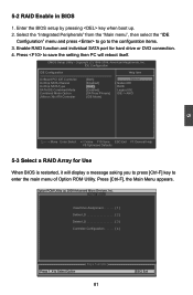
... [Enabled] Legacy IDE Combined Mode Option [SATA as Primary] IDE -> AHCI JMicron 36x ATA Controller [IDE Mode] Move Enter:Select +/-/:Value F10:Save ESC:Exit F1:General Help F9:Optimized Defaults 5-3 Select a RAID Array for hard drive or DVD connection. 4. Option ROM Utility (c) 2008 Advanced Micro Devices, Inc. [ Main Menu ] View Drive Assignment 1 ] Define LD 2 ] Delete LD 3 ] Controller Configuration 4 ] [ Keys Available ] Press 1..4 to save the setting then PC will display...
... [Enabled] Legacy IDE Combined Mode Option [SATA as Primary] IDE -> AHCI JMicron 36x ATA Controller [IDE Mode] Move Enter:Select +/-/:Value F10:Save ESC:Exit F1:General Help F9:Optimized Defaults 5-3 Select a RAID Array for hard drive or DVD connection. 4. Option ROM Utility (c) 2008 Advanced Micro Devices, Inc. [ Main Menu ] View Drive Assignment 1 ] Define LD 2 ] Delete LD 3 ] Controller Configuration 4 ] [ Keys Available ] Press 1..4 to save the setting then PC will display...

English Manual.
Page 104
... a device support disk from a mass storage device manufacturer, press S. * If you have any device support disks from a mass storage device manufacturer, or do not have chosen to continue the specific driver installation. S=Specify Additional Device ENTER=Continue F3=Exit 6. Windows Setup Setup could not determine the type of one or more mass storage devices installed in your system, the following mass storage device(s): * To specify additional SCSI adapters, CD-ROM drivers, or special disk controllers for use with Windows, including...
... a device support disk from a mass storage device manufacturer, press S. * If you have any device support disks from a mass storage device manufacturer, or do not have chosen to continue the specific driver installation. S=Specify Additional Device ENTER=Continue F3=Exit 6. Windows Setup Setup could not determine the type of one or more mass storage devices installed in your system, the following mass storage device(s): * To specify additional SCSI adapters, CD-ROM drivers, or special disk controllers for use with Windows, including...


