User Manual
Page 7
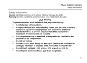
... supplied by the product can be compromised. • Do not work alone. • Do not use test leads if they are damaged. Warning identifies conditions and actions that may damage the 9040. Check test lead continuity. • Do not touch voltages >30 V ac rms, 42 V ac peak, or 60 V ..., fire, or personal injury: • Carefully read all instructions. • Comply with local and national safety codes. Examine the test leads for damaged insulation or exposed metal. Use personal protective equipment (approved rubber gloves, face protection, and flameresistant clothes) to the user.
... supplied by the product can be compromised. • Do not work alone. • Do not use test leads if they are damaged. Warning identifies conditions and actions that may damage the 9040. Check test lead continuity. • Do not touch voltages >30 V ac rms, 42 V ac peak, or 60 V ..., fire, or personal injury: • Carefully read all instructions. • Comply with local and national safety codes. Examine the test leads for damaged insulation or exposed metal. Use personal protective equipment (approved rubber gloves, face protection, and flameresistant clothes) to the user.
User Manual
Page 10
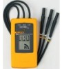
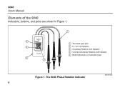
Test lead input jack L1, L2, L3 Indicators Clockwise Rotation LCD Indicator Counter-Clockwise Rotation LCD Indicator Brief Instructions on instrument rear Figure 1. The 9040 Phase Rotation Indicator bbx02f.eps 6 9040 Users Manual Elements of the 9040 Indicators, buttons, and jacks are shown in Figure 1.
Test lead input jack L1, L2, L3 Indicators Clockwise Rotation LCD Indicator Counter-Clockwise Rotation LCD Indicator Brief Instructions on instrument rear Figure 1. The 9040 Phase Rotation Indicator bbx02f.eps 6 9040 Users Manual Elements of the 9040 Indicators, buttons, and jacks are shown in Figure 1.
User Manual
Page 11
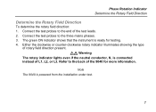
...clockwise or counter-clockwise rotary indicator illuminates showing the type of L1, L2, or L3. Connect the test probes to the end of the 9040 for testing. 4. Connect the test probes to the three mains phases. 3. XW Warning The rotary indicator lights even if the neutral conductor..., N, is powered from the installation under test. 7 Refer to the back of the test leads. 2. Note The 9040 is connected instead of rotary field direction present. Phase Rotation Indicator Determine the Rotary Field Direction Determine the Rotary Field Direction To ...
...clockwise or counter-clockwise rotary indicator illuminates showing the type of L1, L2, or L3. Connect the test probes to the end of the 9040 for testing. 4. Connect the test probes to the three mains phases. 3. XW Warning The rotary indicator lights even if the neutral conductor..., N, is powered from the installation under test. 7 Refer to the back of the test leads. 2. Note The 9040 is connected instead of rotary field direction present. Phase Rotation Indicator Determine the Rotary Field Direction Determine the Rotary Field Direction To ...
