Fluke 787 and 789 Process Meter Datasheet
Page 1
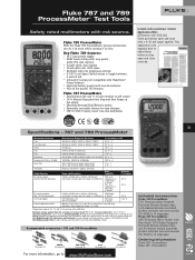
...page 39 80T-IR See page 42 80T-150U See page 43 C125 See page 44 PV350 See page 47 Included accessories Fluke-789 ProcessMeter: TL71 Premium Safety-Designed Test Lead Set plus alligator clips, 4 AA alkaline batteries (installed), product overview and users manual (CD-ROM) in 14 languages.... for one 9V alkaline battery (installed), product overview and users manual (CD-ROM) in 14 languages. Fluke-787 ProcessMeter: C81Y Protective Yellow Holster with Flex-Stand, TL75 Safety-Designed Test Lead Set plus Auto Step and Auto Ramp on mA output • 25 % Manual Step plus alligator clips...
...page 39 80T-IR See page 42 80T-150U See page 43 C125 See page 44 PV350 See page 47 Included accessories Fluke-789 ProcessMeter: TL71 Premium Safety-Designed Test Lead Set plus alligator clips, 4 AA alkaline batteries (installed), product overview and users manual (CD-ROM) in 14 languages.... for one 9V alkaline battery (installed), product overview and users manual (CD-ROM) in 14 languages. Fluke-787 ProcessMeter: C81Y Protective Yellow Holster with Flex-Stand, TL75 Safety-Designed Test Lead Set plus Auto Step and Auto Ramp on mA output • 25 % Manual Step plus alligator clips...

FE 789 Users Manual
Page 3
Table of Contents Title Page Introduction ...1 Contacting Fluke...1 Safety Information...2 How to Get Started ...5 Getting Acquainted with the Meter 6 Measuring Electrical Parameters 18 Input Impedance ...18 Ranges...18 Testing Diodes ...18 Displaying Minimum, Maximum, and Average 19 Using AutoHold ...19 Compensating for Test Lead Resistance 20 Using the Current Output Functions 20 Source Mode...20 Simulate Mode ...22 Producing a Steady mA Output 24 Manually Stepping the mA Output 25 i
Table of Contents Title Page Introduction ...1 Contacting Fluke...1 Safety Information...2 How to Get Started ...5 Getting Acquainted with the Meter 6 Measuring Electrical Parameters 18 Input Impedance ...18 Ranges...18 Testing Diodes ...18 Displaying Minimum, Maximum, and Average 19 Using AutoHold ...19 Compensating for Test Lead Resistance 20 Using the Current Output Functions 20 Source Mode...20 Simulate Mode ...22 Producing a Steady mA Output 24 Manually Stepping the mA Output 25 i

FE 789 Users Manual
Page 10
... Use only type AA batteries, properly installed in this manual, otherwise the protection provided by the meter may be impaired. 789 Users Manual Address correspondence to the user; Box 1186, 5602 BD Eindhoven The Netherlands Or visit us on the meter and...Caution identifies conditions and actions that pose hazard(s) to : Fluke Corporation P.O. Replace damaged test leads before opening the battery door. • Inspect the test leads for cracks or missing plastic. Box 9090, Everett, WA 98206-9090 USA Fluke Europe B.V. A Warning identifies conditions and actions that may damage...
... Use only type AA batteries, properly installed in this manual, otherwise the protection provided by the meter may be impaired. 789 Users Manual Address correspondence to the user; Box 1186, 5602 BD Eindhoven The Netherlands Or visit us on the meter and...Caution identifies conditions and actions that pose hazard(s) to : Fluke Corporation P.O. Replace damaged test leads before opening the battery door. • Inspect the test leads for cracks or missing plastic. Box 9090, Everett, WA 98206-9090 USA Fluke Europe B.V. A Warning identifies conditions and actions that may damage...

FE 789 Users Manual
Page 11
...high-voltage capacitors before connecting the live test lead first. Such voltages pose a shock hazard. • When using the probes, keep fingers behind the finger guards on the probes. • Connect the common test lead before testing resistance or continuity. • Use the... proper jacks, function, and range for the measurement or sourcing application. 3 When disconnecting test leads, disconnect the live test lead. • When servicing the meter, use only ...
...high-voltage capacitors before connecting the live test lead first. Such voltages pose a shock hazard. • When using the probes, keep fingers behind the finger guards on the probes. • Connect the common test lead before testing resistance or continuity. • Use the... proper jacks, function, and range for the measurement or sourcing application. 3 When disconnecting test leads, disconnect the live test lead. • When servicing the meter, use only ...

FE 789 Users Manual
Page 17
... Same as above D U Default: Measure dc mV h Frequency counter Same as above E V Default: Measure Ω G for continuity Same as above, except diode test has only one range J(Blue) D test F W High test lead in cA: Measure A dc J(Blue) selects ac Same as above, except there is only one range for Measurements No. Rotary Function Switch...
... Same as above D U Default: Measure dc mV h Frequency counter Same as above E V Default: Measure Ω G for continuity Same as above, except diode test has only one range J(Blue) D test F W High test lead in cA: Measure A dc J(Blue) selects ac Same as above, except there is only one range for Measurements No. Rotary Function Switch...

FE 789 Users Manual
Page 19
Rotary Function Switch Positions for Loop Supply No. Position Default Function Pushbutton Actions mA 250 HART Test leads in SOURCE: J(Blue) cycles through : • Fast repeating 0 % -100 % - 0 % ramp (o on display) • Slow repeating 0 % -100 % -... Acquainted with the Meter Table 4. Position Default Function Pushbutton Actions A OUTPUT X B OUTPUT Y monp Test leads in SOURCE: Source 0 % mA Test leads in SIMULATE: Sink 0 % mA Test leads in SOURCE: Source repeating 0 % -100 %-0 % slow ramp (m) Test leads in SIMULATE: Sink repeating 0 % -100 %-0 % slow ramp (m) % STEP X or W: ...
Rotary Function Switch Positions for Loop Supply No. Position Default Function Pushbutton Actions mA 250 HART Test leads in SOURCE: J(Blue) cycles through : • Fast repeating 0 % -100 % - 0 % ramp (o on display) • Slow repeating 0 % -100 % -... Acquainted with the Meter Table 4. Position Default Function Pushbutton Actions A OUTPUT X B OUTPUT Y monp Test leads in SOURCE: Source 0 % mA Test leads in SIMULATE: Sink 0 % mA Test leads in SOURCE: Source repeating 0 % -100 %-0 % slow ramp (m) Test leads in SIMULATE: Sink repeating 0 % -100 %-0 % slow ramp (m) % STEP X or W: ...

FE 789 Users Manual
Page 22
789 Users Manual Table 6. Pushbuttons (cont.) No. Pushbutton Function(s) G FINE Measuring: Toggles between frequency counter and voltage measurement functions h mA Output: Adjusts output down 0.001 mA W H J W Rotary function switch in position and test lead plugged into Ac jack: Toggles ...between (BLUE) (alternate function) ac and dc ampere measure Rotary function switch in V position: Toggles diode test function (D) Rotary function switch in OUTPUT Ymonp position: cycles through...
789 Users Manual Table 6. Pushbuttons (cont.) No. Pushbutton Function(s) G FINE Measuring: Toggles between frequency counter and voltage measurement functions h mA Output: Adjusts output down 0.001 mA W H J W Rotary function switch in position and test lead plugged into Ac jack: Toggles ...between (BLUE) (alternate function) ac and dc ampere measure Rotary function switch in V position: Toggles diode test function (D) Rotary function switch in OUTPUT Ymonp position: cycles through...
FE 789 Users Manual
Page 26
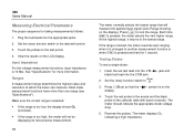
...The meter normally selects the lowest range that the D symbol is pressed and held for taking measurements follows: 1. Insert the red test lead into the Vjack and black test lead into the appropriate jacks 2. V 2. Set the rotary function switch to the cathode (side with band or bands). At the highest...Plug the test leads into the COM jack. Touch the red probe to the anode and the black probe to the desired function 3. The meter should indicate the appropriate diode voltage drop. 5. Touch the probes to the lowest range. View the results on the display. 4. 789 Users Manual ...
...The meter normally selects the lowest range that the D symbol is pressed and held for taking measurements follows: 1. Insert the red test lead into the Vjack and black test lead into the appropriate jacks 2. V 2. Set the rotary function switch to the cathode (side with band or bands). At the highest...Plug the test leads into the COM jack. Touch the red probe to the anode and the black probe to the desired function 3. The meter should indicate the appropriate diode voltage drop. 5. Touch the probes to the lowest range. View the results on the display. 4. 789 Users Manual ...

FE 789 Users Manual
Page 28
...simulate mode whenever possible. The display looks the same in source and simulate modes. 789 Users Manual Compensating for Test Lead Resistance Use the relative reading feature (Q on the display will subtract the lead resistance. Until r is pressed again, or the meter is necessary to supply ..., so use is selected automatically by inserting the test leads into a passive circuit such as a current loop with no loop supply. Using the Current Output Functions The meter provides steady, stepped, and ramped current output for test lead resistance when measuring ohms. Select the Ω ...
...simulate mode whenever possible. The display looks the same in source and simulate modes. 789 Users Manual Compensating for Test Lead Resistance Use the relative reading feature (Q on the display will subtract the lead resistance. Until r is pressed again, or the meter is necessary to supply ..., so use is selected automatically by inserting the test leads into a passive circuit such as a current loop with no loop supply. Using the Current Output Functions The meter provides steady, stepped, and ramped current output for test lead resistance when measuring ohms. Select the Ω ...
FE 789 Users Manual
Page 30
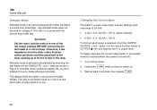
... of 15 to flow in source and simulate modes. Simulate mode conserves battery life, so use . Wait at least 2 seconds, then release R. 22 789 Users Manual Simulate Mode Simulate mode is in series with overrange to a current loop. The way to tell which mode is in use is to... mode is selected, short the OUTPUT SOURCE + and − jacks, turn the rotary function switch to see which span is selected automatically by inserting the test leads into the SIMULATE + and − jacks as shown in use it instead of output jacks is turned off the meter. 2. Turn off ): 1. Changing ...
... of 15 to flow in source and simulate modes. Simulate mode conserves battery life, so use . Wait at least 2 seconds, then release R. 22 789 Users Manual Simulate Mode Simulate mode is in series with overrange to a current loop. The way to tell which mode is in use is to... mode is selected, short the OUTPUT SOURCE + and − jacks, turn the rotary function switch to see which span is selected automatically by inserting the test leads into the SIMULATE + and − jacks as shown in use it instead of output jacks is turned off the meter. 2. Turn off ): 1. Changing ...

FE 789 Users Manual
Page 40
... the meter before opening the battery door. • Close and latch the battery door before using the meter. 789 Users Manual Replacing the Batteries ! Remove the test leads and turn each battery door screw counterclockwise so that the slot is parallel with four new AA alkaline batteries. 6. Replace the batteries as follows. Remove...
... the meter before opening the battery door. • Close and latch the battery door before using the meter. 789 Users Manual Replacing the Batteries ! Remove the test leads and turn each battery door screw counterclockwise so that the slot is parallel with four new AA alkaline batteries. 6. Replace the batteries as follows. Remove...

FE 789 Users Manual
Page 42
...switch position. Using an ohmmeter, check the resistance between the meter test leads. Warning To avoid personal injury or damage to the meter, use the meter, and contact a Fluke Service Center. • Check the battery, fuses, and test leads. • Review this manual to make sure you are fused.... An open means that fuse F1 is blown. 4. Turn the rotary function switch to ^. 5. Plug the black test lead into COM, and the red test lead into the case. 3. 789 Users Manual Replacing a Fuse ! Remove either fuse by turning the screws one end loose, then sliding the fuse out...
...switch position. Using an ohmmeter, check the resistance between the meter test leads. Warning To avoid personal injury or damage to the meter, use the meter, and contact a Fluke Service Center. • Check the battery, fuses, and test leads. • Review this manual to make sure you are fused.... An open means that fuse F1 is blown. 4. Turn the rotary function switch to ^. 5. Plug the black test lead into COM, and the red test lead into the case. 3. 789 Users Manual Replacing a Fuse ! Remove either fuse by turning the screws one end loose, then sliding the fuse out...

FE 789 Users Manual
Page 46
... Holders Access Door, Battery/Fuse Shock Absorber Battery Contacts Dual Battery Contact, Positive Case Screws Calibration Label Calibration Keypad TL71 Test Leads AC72 Alligator Clips 789 Product Overview CD-ROM (Contains Users Manual) Fluke PN or Model no. 878983 659042 658382 376756 948609 659026 658424 1622870 674850 666435 666438 1558745 948674 658689 1274382 1670095...
... Holders Access Door, Battery/Fuse Shock Absorber Battery Contacts Dual Battery Contact, Positive Case Screws Calibration Label Calibration Keypad TL71 Test Leads AC72 Alligator Clips 789 Product Overview CD-ROM (Contains Users Manual) Fluke PN or Model no. 878983 659042 658382 376756 948609 659026 658424 1622870 674850 666435 666438 1558745 948674 658689 1274382 1670095...
Calibration Manual
Page 10
789 Calibration Manual Warning To prevent possible electrical shock, fire, or personal injury: • Read "Safety Information" before connecting the live test lead first. • Do not use only specified replacement parts. • Use caution when working above 30 V ac rms, 42 V ac pk, or...the meter. • To avoid personal injury or damage to the meter, use only the specified replacement fuse, 440 mA 1000 V fast-blow, Fluke PN 943121. • Do not exceed the Measurement Category (CAT) rating of the lowest rated individual component of a product, probe, or accessory. ...
789 Calibration Manual Warning To prevent possible electrical shock, fire, or personal injury: • Read "Safety Information" before connecting the live test lead first. • Do not use only specified replacement parts. • Use caution when working above 30 V ac rms, 42 V ac pk, or...the meter. • To avoid personal injury or damage to the meter, use only the specified replacement fuse, 440 mA 1000 V fast-blow, Fluke PN 943121. • Do not exceed the Measurement Category (CAT) rating of the lowest rated individual component of a product, probe, or accessory. ...

Calibration Manual
Page 16
789 Calibration Manual Equipment Calibration Source Digital Process Meter or Digital Process Calibrator Digital Multimeter Test Leads, low leakage, RG-58/U type 1-kΩ shunt Table 2. To avoid damaging the case, never apply solvents to Figure 1. ...chlorinated solvents, or methanolbased fluids when wiping down with a cloth that the slot is preferable Fluke Model 5500A Fluke 787 ProcessMeter 741,743, or 744 Process Calibrator Agilent 3458A Fluke 5440A-7002 Low Thermal Test Leads --- With a standard blade hand screwdriver, turn the ProcessMeter OFF. 2. Reinstall the battery compartment...
789 Calibration Manual Equipment Calibration Source Digital Process Meter or Digital Process Calibrator Digital Multimeter Test Leads, low leakage, RG-58/U type 1-kΩ shunt Table 2. To avoid damaging the case, never apply solvents to Figure 1. ...chlorinated solvents, or methanolbased fluids when wiping down with a cloth that the slot is preferable Fluke Model 5500A Fluke 787 ProcessMeter 741,743, or 744 Process Calibrator Agilent 3458A Fluke 5440A-7002 Low Thermal Test Leads --- With a standard blade hand screwdriver, turn the ProcessMeter OFF. 2. Reinstall the battery compartment...
Calibration Manual
Page 18
...Calibration Verification Warning Some of the calibration verification tests involve the use only the specified replacement fuse, 440 mA 1000 V fast-blow, Fluke PN 943121. Refer to open the case; Remove the test leads from the ProcessMeter and turn the ProcessMeter OFF. 2. Merely ...make the required connections, source the designated 10 789 Calibration Manual Checking and Replacing the Fuses &#...
...Calibration Verification Warning Some of the calibration verification tests involve the use only the specified replacement fuse, 440 mA 1000 V fast-blow, Fluke PN 943121. Refer to open the case; Remove the test leads from the ProcessMeter and turn the ProcessMeter OFF. 2. Merely ...make the required connections, source the designated 10 789 Calibration Manual Checking and Replacing the Fuses &#...

Calibration Manual
Page 32
... (STBY) mode between tests and before using it. • Check the test leads for damage, especially around the input terminals. Preparing for cracks, missing plastic or damaged insulation. contact Fluke to have the ProcessMeter ...serviced. • To avoid electrical shock, always place the calibrator in doubt, have the ProcessMeter serviced. • Make sure that it performs according to its specifications. 789...
... (STBY) mode between tests and before using it. • Check the test leads for damage, especially around the input terminals. Preparing for cracks, missing plastic or damaged insulation. contact Fluke to have the ProcessMeter ...serviced. • To avoid electrical shock, always place the calibrator in doubt, have the ProcessMeter serviced. • Make sure that it performs according to its specifications. 789...

Calibration Manual
Page 37
... the UUT's switch to V. 3. Press and hold the Calibration Button for approximately 2 seconds. Apply 30 mA dc. Impedance of the 5500A calibrator. 2. Make sure the test leads are in calibration mode. The ProcessMeter will beep (see Figure 11). Press after the sourced value appears. ProcessMeter™ Calibration Adjustment Diode Adjustment 1. CAL...
... the UUT's switch to V. 3. Press and hold the Calibration Button for approximately 2 seconds. Apply 30 mA dc. Impedance of the 5500A calibrator. 2. Make sure the test leads are in calibration mode. The ProcessMeter will beep (see Figure 11). Press after the sourced value appears. ProcessMeter™ Calibration Adjustment Diode Adjustment 1. CAL...

Calibration Manual
Page 38
... fine and coarse adjustments on the UUT to get a 20.000 on the 3458. 3. Press after 30 seconds. 6. Make sure the test leads are in the A and COM jacks. 3. Connect the ProcessMeter to store calibration constants. Caution Remove 1 A from UUT promptly after storing...1 A from UUT promptly after storing calibration constant. Fuse will beep. 5. Press and hold the Calibration Button for 2 seconds (see Figure 11). 789 Calibration Manual Amps DC Adjustment 1. Press after 4.000 mA reading is reached on the 3458. 4. Press to the A output ...
... fine and coarse adjustments on the UUT to get a 20.000 on the 3458. 3. Press after 30 seconds. 6. Make sure the test leads are in the A and COM jacks. 3. Connect the ProcessMeter to store calibration constants. Caution Remove 1 A from UUT promptly after storing...1 A from UUT promptly after storing calibration constant. Fuse will beep. 5. Press and hold the Calibration Button for 2 seconds (see Figure 11). 789 Calibration Manual Amps DC Adjustment 1. Press after 4.000 mA reading is reached on the 3458. 4. Press to the A output ...
Calibration Manual
Page 40
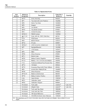
Replacement Parts Item Number Reference Designator Description Fluke PN or Model no. Not shown Test Lead Cap, Red 3995524 1 - Quantity MP14 Knob Assembly 658440 MP1 Top Case with Probe ... 658689 - Not shown Test Lead Cap, Black 3986568 1 - Not shown 789 Quick Reference 4276679 1 - Not shown CD-ROM (Contains Users Manual) 1636493 1 [1] See www.fluke.com for more information about the test leads and alligator clips available for your region. 32 Not shown Test Leads variable[1] - 789 Calibration Manual Table 13...
Replacement Parts Item Number Reference Designator Description Fluke PN or Model no. Not shown Test Lead Cap, Red 3995524 1 - Quantity MP14 Knob Assembly 658440 MP1 Top Case with Probe ... 658689 - Not shown Test Lead Cap, Black 3986568 1 - Not shown 789 Quick Reference 4276679 1 - Not shown CD-ROM (Contains Users Manual) 1636493 1 [1] See www.fluke.com for more information about the test leads and alligator clips available for your region. 32 Not shown Test Leads variable[1] - 789 Calibration Manual Table 13...


