Fluke 787 and 789 Process Meter Datasheet
Page 1
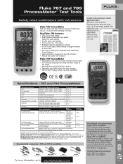
... Flex-Stand, TL75 Safety-Designed Test Lead Set plus alligator clips, one year after calibration Maximum voltage applied between 4 and 20 mA • Infrared I/O serial port compatible with FlukeView® Forms Software • Improved battery power with four AA batteries • Plus all the proven 787 features Fluke 787 ProcessMeter • Simultaneous mA and...
... Flex-Stand, TL75 Safety-Designed Test Lead Set plus alligator clips, one year after calibration Maximum voltage applied between 4 and 20 mA • Infrared I/O serial port compatible with FlukeView® Forms Software • Improved battery power with four AA batteries • Plus all the proven 787 features Fluke 787 ProcessMeter • Simultaneous mA and...
FE 787 Users Manual
Page 3
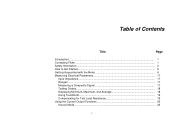
Table of Contents Title Page Introduction...1 Contacting Fluke ...1 Safety Information ...2 How to Get Started...5 Getting Acquainted with the Meter 6 Measuring Electrical Parameters 17 Input Impedance...17 Ranges ...17 Measuring a Composite Signal 17 Testing Diodes...18 Displaying Minimum, Maximum, and Average 18 Using TouchHold ...19 Compensating for Test Lead Resistance 19 Using the Current Output Functions 20 Source Mode ...20 i
Table of Contents Title Page Introduction...1 Contacting Fluke ...1 Safety Information ...2 How to Get Started...5 Getting Acquainted with the Meter 6 Measuring Electrical Parameters 17 Input Impedance...17 Ranges ...17 Measuring a Composite Signal 17 Testing Diodes...18 Displaying Minimum, Maximum, and Average 18 Using TouchHold ...19 Compensating for Test Lead Resistance 19 Using the Current Output Functions 20 Source Mode ...20 i
FE 787 Users Manual
Page 5
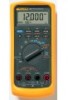
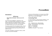
... parts or spares, see Table 13 near the end of this manual, and a laminated Quick Reference Card that fits inside the holster. Your Fluke 787 ProcessMeter™ (referred to test process instruments. If the meter is damaged or something is shipped with a Flex-Stand™ holster, one ...set of TL75 test leads, one set of purchase immediately. Contact your Fluke distributor for measuring electrical parameters and supplying steady or ramping current to as "the meter") is a handheld, battery-operated...
... parts or spares, see Table 13 near the end of this manual, and a laminated Quick Reference Card that fits inside the holster. Your Fluke 787 ProcessMeter™ (referred to test process instruments. If the meter is damaged or something is shipped with a Flex-Stand™ holster, one ...set of TL75 test leads, one set of purchase immediately. Contact your Fluke distributor for measuring electrical parameters and supplying steady or ramping current to as "the meter") is a handheld, battery-operated...
FE 787 Users Manual
Page 7
...guidelines: • Use caution when working above 30V ac rms, 42V ac pk, or 60V dc. When you connect the live test lead first. 3 Check test leads continuity. Protection may be impaired. Such voltages pose a shock hazard. • When using the probes, keep your measurement or sourcing application.... Replace damaged test leads before you use the meter. • Do not use only specified replacement parts. • Make sure the battery door is closed and ...
...guidelines: • Use caution when working above 30V ac rms, 42V ac pk, or 60V dc. When you connect the live test lead first. 3 Check test leads continuity. Protection may be impaired. Such voltages pose a shock hazard. • When using the probes, keep your measurement or sourcing application.... Replace damaged test leads before you use the meter. • Do not use only specified replacement parts. • Make sure the battery door is closed and ...
FE 787 Users Manual
Page 13
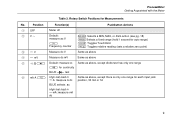
Rotary Switch Positions for each input jack cA: measure A dc position, 30 mA or 1A BLUE selects ac High test lead in Same as above, except there is only one range for Measurements No. Position Function(s) Pushbutton Actions A OFF Meter off B VA Default: measure ac V F Frequency ... dc mV Same as above E O Default: measure Ω Same as above, except diode test has only one range T for continuity BLUE D test F mA A L High test lead in dmA: measure mA dc 9 ProcessMeter Getting Acquainted with the Meter Table 3.
Rotary Switch Positions for each input jack cA: measure A dc position, 30 mA or 1A BLUE selects ac High test lead in Same as above, except there is only one range for Measurements No. Position Function(s) Pushbutton Actions A OFF Meter off B VA Default: measure ac V F Frequency ... dc mV Same as above E O Default: measure Ω Same as above, except diode test has only one range T for continuity BLUE D test F mA A L High test lead in dmA: measure mA dc 9 ProcessMeter Getting Acquainted with the Meter Table 3.
FE 787 Users Manual
Page 15
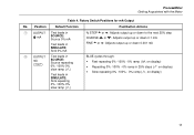
... 25% step COARSE Z or Y: Adjusts output up or down 0.1 mA FINE X or W: Adjusts output up or down 0.001 mA B OUTPUT Test leads in mA J SOURCE: Source repeating 0% -100%-0% slow ramp (E) Test leads in SIMULATE: Sink repeating 0% -100%-0% slow ramp (E) BLUE cycles through: • Fast repeating 0% -100% - 0% ramp (P on display) • Repeating 0% -100...
... 25% step COARSE Z or Y: Adjusts output up or down 0.1 mA FINE X or W: Adjusts output up or down 0.001 mA B OUTPUT Test leads in mA J SOURCE: Source repeating 0% -100%-0% slow ramp (E) Test leads in SIMULATE: Sink repeating 0% -100%-0% slow ramp (E) BLUE cycles through: • Fast repeating 0% -100% - 0% ramp (P on display) • Repeating 0% -100...
FE 787 Users Manual
Page 16
Pushbuttons ee003f.eps Table 5. 787 Users Manual No. Pushbuttons Function(s) Toggles the backlight Rotary switch in mA A Lposition and test lead plugged into c A jack: Toggles between ac and dc ampere measure Rotary switch in O position: Selects diode test function (D) Rotary switch in OUTPUT mA Jposition: Cycles ...
Pushbuttons ee003f.eps Table 5. 787 Users Manual No. Pushbuttons Function(s) Toggles the backlight Rotary switch in mA A Lposition and test lead plugged into c A jack: Toggles between ac and dc ampere measure Rotary switch in O position: Selects diode test function (D) Rotary switch in OUTPUT mA Jposition: Cycles ...
FE 787 Users Manual
Page 21
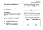
... ac with a dc bias, you press K and hold it for 1 second. Press Kif you press K, the meter selects the next higher range. Plug the test leads into the appropriate jacks. 2. Set the rotary knob. 3. If you have more information. ProcessMeter Measuring Electrical Parameters The meter normally automatically selects the lowest range...
... ac with a dc bias, you press K and hold it for 1 second. Press Kif you press K, the meter selects the next higher range. Plug the test leads into the appropriate jacks. 2. Set the rotary knob. 3. If you have more information. ProcessMeter Measuring Electrical Parameters The meter normally automatically selects the lowest range...
FE 787 Users Manual
Page 22
... suspend recording; In MIN MAX recording, press I again to the cathode (side with band or bands). Insert the red test lead into the Vjack and black test lead into the COM jack. 2. Touch the red probe to the anode and the black probe to resume recording. 18 If MIN... the average of all measurements. Auto power-off during MIN MAX recording. press I to erase stored measurements and exit . Reverse the probes. 787 Users Manual Testing Diodes To test a single diode: 1. The meter should display OL, indicating a high impedance. 6. Press M again to turn the meter...
... suspend recording; In MIN MAX recording, press I again to the cathode (side with band or bands). Insert the red test lead into the Vjack and black test lead into the COM jack. 2. Touch the red probe to the anode and the black probe to resume recording. 18 If MIN... the average of all measurements. Auto power-off during MIN MAX recording. press I to erase stored measurements and exit . Reverse the probes. 787 Users Manual Testing Diodes To test a single diode: 1. The meter should display OL, indicating a high impedance. 6. Press M again to turn the meter...
FE 787 Users Manual
Page 23
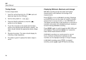
... display with each new stable reading (except in which it is present. Select the Ω measure function, touch the test leads together, then press C. Warning To avoid possible electric shock, do not use TouchHold to determine if dangerous voltage is difficult to... look at the display. TouchHold will subtract the lead resistance. 19 A common use TouchHold. ! ProcessMeter Measuring Electrical Parameters Compensating for test lead resistance when measuring Ω. Until you to take measurements in situations in the frequency ...
... display with each new stable reading (except in which it is present. Select the Ω measure function, touch the test leads together, then press C. Warning To avoid possible electric shock, do not use TouchHold to determine if dangerous voltage is difficult to... look at the display. TouchHold will subtract the lead resistance. 19 A common use TouchHold. ! ProcessMeter Measuring Electrical Parameters Compensating for test lead resistance when measuring Ω. Until you to take measurements in situations in the frequency ...
FE 787 Users Manual
Page 24
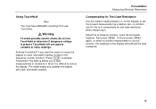
... in source and simulate modes. The way to tell which pair of output jacks is selected automatically by inserting the test leads into a passive circuit such as shown in use. 20 787 Users Manual Using the Current Output Functions The meter provides steady, stepped, and ramped current output for testing 0-20 mA...
... in source and simulate modes. The way to tell which pair of output jacks is selected automatically by inserting the test leads into a passive circuit such as shown in use. 20 787 Users Manual Using the Current Output Functions The meter provides steady, stepped, and ramped current output for testing 0-20 mA...
FE 787 Users Manual
Page 26
787 Users Manual Simulate Mode Simulate mode is selected automatically by inserting the test leads into the SIMULATE + and − jacks as shown in Figure 8. Simulate mode is so named because the meter simulates a current loop transmitter. Changing the Current ... + and − jacks, turn the rotary switch to see which span is turned off the meter. 2. Hold down the Kpushbutton while you connect the test leads to 30V is in source and simulate modes. Turn off ): 1.
787 Users Manual Simulate Mode Simulate mode is selected automatically by inserting the test leads into the SIMULATE + and − jacks as shown in Figure 8. Simulate mode is so named because the meter simulates a current loop transmitter. Changing the Current ... + and − jacks, turn the rotary switch to see which span is turned off the meter. 2. Hold down the Kpushbutton while you connect the test leads to 30V is in source and simulate modes. Turn off ): 1.
FE 787 Users Manual
Page 32
...Holster and Flex-Stand The meter is equipped with a damp cloth and detergent; For maintenance procedures not described in this manual, contact a Fluke Service Center. To preserve battery life: • Use current simulation instead of the holster with a snap-on holster that it . ...life. Repair, calibration, servicing not covered in this manual must be performed by qualified personnel. 787 Users Manual Battery Life WWarning To avoid false readings, which could lead to ensure that absorbs shocks and protects the meter from scratches when carrying the meter. Maintenance This...
...Holster and Flex-Stand The meter is equipped with a damp cloth and detergent; For maintenance procedures not described in this manual, contact a Fluke Service Center. To preserve battery life: • Use current simulation instead of the holster with a snap-on holster that it . ...life. Repair, calibration, servicing not covered in this manual must be performed by qualified personnel. 787 Users Manual Battery Life WWarning To avoid false readings, which could lead to ensure that absorbs shocks and protects the meter from scratches when carrying the meter. Maintenance This...
FE 787 Users Manual
Page 34
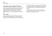
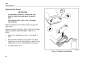
... screw counterclockwise so that the slot is parallel with the screw picture molded into the case. 3. Replacing the Battery ee007f.eps Remove the test leads and set the rotary switch to Figure 10. Lift off the battery door. 30 Figure 10. Close and latch the battery door before you... open the battery door. Use an alkaline 9V battery, type ANSI/NEDA 1604A or IEC 6LR61. 1. 787 Users Manual Replacing the Battery ! Warning To avoid electrical shock, remove test leads from the meter before you use the meter. Replace the battery as follows. Remove test...
... screw counterclockwise so that the slot is parallel with the screw picture molded into the case. 3. Replacing the Battery ee007f.eps Remove the test leads and set the rotary switch to Figure 10. Lift off the battery door. 30 Figure 10. Close and latch the battery door before you... open the battery door. Use an alkaline 9V battery, type ANSI/NEDA 1604A or IEC 6LR61. 1. 787 Users Manual Replacing the Battery ! Warning To avoid electrical shock, remove test leads from the meter before you use the meter. Replace the battery as follows. Remove test...
FE 787 Users Manual
Page 35
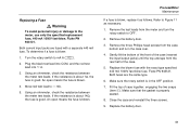
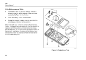
...as necessary: 1. Replace the battery door. 31 To determine if a fuse is properly seated. 8. Using an ohmmeter, check the resistance between the meter test leads. An open means the fuse is blown. Remove the battery door. 3. Both fuses are fused with the exact type specified: 440 mA 1000V fast-blow... fuse, Fluke PN 943121. Close the case and reinstall the three screws. 9. An open means the fuse is blown. 4. Gently lift the bottom of the front...
...as necessary: 1. Replace the battery door. 31 To determine if a fuse is properly seated. 8. Using an ohmmeter, check the resistance between the meter test leads. An open means the fuse is blown. Remove the battery door. 3. Both fuses are fused with the exact type specified: 440 mA 1000V fast-blow... fuse, Fluke PN 943121. Close the case and reinstall the three screws. 9. An open means the fuse is blown. 4. Gently lift the bottom of the front...
FE 787 Users Manual
Page 36
...If the warranty has lapsed, the meter will be repaired or replaced (at Fluke's option) and returned at no further attempt to use the meter, and contact a Fluke Service Center. • Check the battery, fuses, and test leads. • Review this manual to make sure you are using the correct... jacks and rotary switch position. Replacing a Fuse ee012f.eps 32 787 Users Manual If the Meter does not Work •...
...If the warranty has lapsed, the meter will be repaired or replaced (at Fluke's option) and returned at no further attempt to use the meter, and contact a Fluke Service Center. • Check the battery, fuses, and test leads. • Review this manual to make sure you are using the correct... jacks and rotary switch position. Replacing a Fuse ee012f.eps 32 787 Users Manual If the Meter does not Work •...
FE 787 Users Manual
Page 38
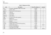
787 Users Manual Item BT1 CG81Y ! Replacement Parts Description 9V battery, ANSI/NEDA 1604A or IEC 6LR61 Holster, Yellow Fuse, 440 mA, 1000V fast-blow Case top Case bottom Case screw Non-skid foot O-ring for input/output receptacle Battery door Battery door fasteners Keypad Standard test lead... set Alligator clips for use with TL75 test lead set Industrial test lead set Product Overview Manual Users Manual (CD-ROM) Calibration Manual (not shown) Fluke PN or Model no. 614487 CG81G 943121 619962 619939 832246...
787 Users Manual Item BT1 CG81Y ! Replacement Parts Description 9V battery, ANSI/NEDA 1604A or IEC 6LR61 Holster, Yellow Fuse, 440 mA, 1000V fast-blow Case top Case bottom Case screw Non-skid foot O-ring for input/output receptacle Battery door Battery door fasteners Keypad Standard test lead... set Alligator clips for use with TL75 test lead set Industrial test lead set Product Overview Manual Users Manual (CD-ROM) Calibration Manual (not shown) Fluke PN or Model no. 614487 CG81G 943121 619962 619939 832246...
FE 787 Users Manual
Page 39
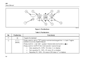
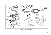
MP85 F2 F1 MP8 MP86 H2, 3, 4 BT1 H5, 6 ProcessMeter Replacement Parts and Accessories S1 TL20 (Option) Industrial Test Lead Set AC70A Alligator Clips TL75 Test Lead Set Product Overview Manual Holster CG81Y MP89, 90 MP92 CD-ROM (Users Manual) Figure 12. Replacement Parts ee015c.eps 35
MP85 F2 F1 MP8 MP86 H2, 3, 4 BT1 H5, 6 ProcessMeter Replacement Parts and Accessories S1 TL20 (Option) Industrial Test Lead Set AC70A Alligator Clips TL75 Test Lead Set Product Overview Manual Holster CG81Y MP89, 90 MP92 CD-ROM (Users Manual) Figure 12. Replacement Parts ee015c.eps 35
FE 787 Users Manual
Page 47
Diodes, testing, 18 Display, 15 43 Calibrating the meter, 28 Compensating for test lead resistance, 19 Composite Signals, 17 Index Current output Compliance, 24 Load impedance, 24 Ramping, auto, 26 Simulating a transmitter, 22 Sourcing, 20 Span (4-20 mA or 0-20 mA), 22 Steady, 24 Stepping, auto, 26 Stepping, manually, 25 With external loop supply, 22 -D- Auto Ramping, 17, 26 Ranging, 17 Stepping, 17 -B- Battery Replacement, 30 Buttons, 12 -C- -A-
Diodes, testing, 18 Display, 15 43 Calibrating the meter, 28 Compensating for test lead resistance, 19 Composite Signals, 17 Index Current output Compliance, 24 Load impedance, 24 Ramping, auto, 26 Simulating a transmitter, 22 Sourcing, 20 Span (4-20 mA or 0-20 mA), 22 Steady, 24 Stepping, auto, 26 Stepping, manually, 25 With external loop supply, 22 -D- Auto Ramping, 17, 26 Ranging, 17 Stepping, 17 -B- Battery Replacement, 30 Buttons, 12 -C- -A-
