
Fluke 787 and 789 Process Meter Datasheet
Page 1
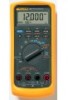
... compatible with FlukeView® Forms Software • Improved battery power with four AA batteries • Plus all the proven 787 features Fluke 787 ProcessMeter • Simultaneous mA and % of 18 °C to 28 °C, for resistance < approx. 100 ohms ...) in 14 languages. Fluke 789 ProcessMeter With the Fluke 789 ProcessMeter, process technicians can do a lot more information, go to wwwww.MwyF.MlukyeFSltuokree.Scotmore.com Fluke-787 ProcessMeter: C81Y Protective Yellow Holster with mA source. Ordering information Fluke-789 ProcessMeter Fluke-787 ProcessMeter For more while ...
... compatible with FlukeView® Forms Software • Improved battery power with four AA batteries • Plus all the proven 787 features Fluke 787 ProcessMeter • Simultaneous mA and % of 18 °C to 28 °C, for resistance < approx. 100 ohms ...) in 14 languages. Fluke 789 ProcessMeter With the Fluke 789 ProcessMeter, process technicians can do a lot more information, go to wwwww.MwyF.MlukyeFSltuokree.Scotmore.com Fluke-787 ProcessMeter: C81Y Protective Yellow Holster with mA source. Ordering information Fluke-789 ProcessMeter Fluke-787 ProcessMeter For more while ...
FE 787 Users Manual
Page 3
Table of Contents Title Page Introduction...1 Contacting Fluke ...1 Safety Information ...2 How to Get Started...5 Getting Acquainted with the Meter 6 Measuring Electrical Parameters 17 Input Impedance...17 Ranges ...17 Measuring a Composite Signal 17 Testing Diodes...18 Displaying Minimum, Maximum, and Average 18 Using TouchHold ...19 Compensating for Test Lead Resistance 19 Using the Current Output Functions 20 Source Mode ...20 i
Table of Contents Title Page Introduction...1 Contacting Fluke ...1 Safety Information ...2 How to Get Started...5 Getting Acquainted with the Meter 6 Measuring Electrical Parameters 17 Input Impedance...17 Ranges ...17 Measuring a Composite Signal 17 Testing Diodes...18 Displaying Minimum, Maximum, and Average 18 Using TouchHold ...19 Compensating for Test Lead Resistance 19 Using the Current Output Functions 20 Source Mode ...20 i
FE 787 Users Manual
Page 7
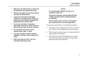
... operates abnormally. Replace damaged test leads before testing resistance or continuity. Such voltages pose a shock hazard. • When using the probes, keep your measurement or sourcing application. When you disconnect test leads, disconnect the live test lead. • Make sure the battery door is closed and latched before you operate the...
... operates abnormally. Replace damaged test leads before testing resistance or continuity. Such voltages pose a shock hazard. • When using the probes, keep your measurement or sourcing application. When you disconnect test leads, disconnect the live test lead. • Make sure the battery door is closed and latched before you operate the...
FE 787 Users Manual
Page 9
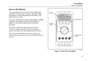
Later, use . If you can use the Quick Reference Card to refresh your meter. Fluke 787 ProcessMeter ee014f.eps 5 Display Rotary Switch ProcessMeter How to Get Started If you are unfamiliar with the Meter," and begin using your memory about ... Electrical Parameters" in addition to the sections referenced in the previous paragraph. How to Get Started 787 PROCESSMETER MIN MAX % STEP RANGE COARSE REL HOLD H FINE Hz mV V mA A OUTPUT mA V mA OFF OUTPUT 0-24mA SOURCE + SIMULATE + A mA COM V 0.44A (1A /30 sec) FUSED 30mA FUSED CAT 1000V Pushbuttons Input/Output...
Later, use . If you can use the Quick Reference Card to refresh your meter. Fluke 787 ProcessMeter ee014f.eps 5 Display Rotary Switch ProcessMeter How to Get Started If you are unfamiliar with the Meter," and begin using your memory about ... Electrical Parameters" in addition to the sections referenced in the previous paragraph. How to Get Started 787 PROCESSMETER MIN MAX % STEP RANGE COARSE REL HOLD H FINE Hz mV V mA A OUTPUT mA V mA OFF OUTPUT 0-24mA SOURCE + SIMULATE + A mA COM V 0.44A (1A /30 sec) FUSED 30mA FUSED CAT 1000V Pushbuttons Input/Output...
FE 787 Users Manual
Page 10
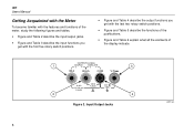
787 Users Manual Getting Acquainted with the Meter To become familiar with the features and functions of the meter, study the following figures and tables. • ... the functions of the pushbuttons. • Figure and Table 6 explain what all the elements of the display indicate. Input/Output Jacks ee001f.eps 6 OUTPUT 0-24mA 1 SOURCE + SIMULATE + 3 A mA COM V 0.44A (1A /30 sec) FUSED 30mA FUSED CAT 1000V 2 4 Figure 2.
787 Users Manual Getting Acquainted with the Meter To become familiar with the features and functions of the meter, study the following figures and tables. • ... the functions of the pushbuttons. • Figure and Table 6 explain what all the elements of the display indicate. Input/Output Jacks ee001f.eps 6 OUTPUT 0-24mA 1 SOURCE + SIMULATE + 3 A mA COM V 0.44A (1A /30 sec) FUSED 30mA FUSED CAT 1000V 2 4 Figure 2.
FE 787 Users Manual
Page 11
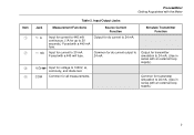
....) Common for up to 30 mA. Input for dc current output to 1000V, Ω, continuity, and diode test. Input/Output Jacks Jack c A d mA Measurement Functions Source Current Function Input for current to 440 mA continuous. (1A for transmitter simulation to 24 mA. Output for dc current to 24 mA. (Use in...
....) Common for up to 30 mA. Input for dc current output to 1000V, Ω, continuity, and diode test. Input/Output Jacks Jack c A d mA Measurement Functions Source Current Function Input for current to 440 mA continuous. (1A for transmitter simulation to 24 mA. Output for dc current to 24 mA. (Use in...
FE 787 Users Manual
Page 15
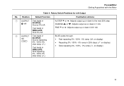
ProcessMeter Getting Acquainted with the Meter Table 4. Position Default Function Pushbutton Actions A OUTPUT Test leads in [ mA SOURCE: Source 0% mA Test leads in SIMULATE: Sink 0% mA % STEP X or W: Adjusts output up or down to the next 25% step COARSE Z or ...Y: Adjusts output up or down 0.1 mA FINE X or W: Adjusts output up or down 0.001 mA B OUTPUT Test leads in mA J SOURCE: Source repeating 0% -100%-0% slow ramp (E) Test leads in SIMULATE: Sink repeating 0% -100%-0% slow ramp (E) BLUE cycles through: • Fast repeating 0% -100% - 0% ramp (P on...
ProcessMeter Getting Acquainted with the Meter Table 4. Position Default Function Pushbutton Actions A OUTPUT Test leads in [ mA SOURCE: Source 0% mA Test leads in SIMULATE: Sink 0% mA % STEP X or W: Adjusts output up or down to the next 25% step COARSE Z or ...Y: Adjusts output up or down 0.1 mA FINE X or W: Adjusts output up or down 0.001 mA B OUTPUT Test leads in mA J SOURCE: Source repeating 0% -100%-0% slow ramp (E) Test leads in SIMULATE: Sink repeating 0% -100%-0% slow ramp (E) BLUE cycles through: • Fast repeating 0% -100% - 0% ramp (P on...
FE 787 Users Manual
Page 19
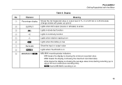
... I MINMAXAVGR MIN MAX recording status indicators: MIN means the display is showing the average value since starting recording (up option) B OUTPUT Lights when mA output (source or simulate) is active C D Lights in diode test function D S Lights in a 0-20 mA or 4-20 mA scale (change scales with the Meter Table 6. Rmeans MIN...
... I MINMAXAVGR MIN MAX recording status indicators: MIN means the display is showing the average value since starting recording (up option) B OUTPUT Lights when mA output (source or simulate) is active C D Lights in diode test function D S Lights in a 0-20 mA or 4-20 mA scale (change scales with the Meter Table 6. Rmeans MIN...
FE 787 Users Manual
Page 22
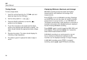
... M for over 40 hours, minimum and maximum readings are stored until you turn MIN MAX off , switch to the cathode (side with band or bands). 787 Users Manual Testing Diodes To test a single diode: 1. press I to O. 3. Touch the red probe to the anode and the black probe to another measurement or...
... M for over 40 hours, minimum and maximum readings are stored until you turn MIN MAX off , switch to the cathode (side with band or bands). 787 Users Manual Testing Diodes To test a single diode: 1. press I to O. 3. Touch the red probe to the anode and the black probe to another measurement or...
FE 787 Users Manual
Page 23
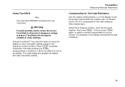
TouchHold will subtract the lead resistance. 19 Until you press C again, or switch to another measurement or source function, the readings on each new stable reading. This feature allows you want the meter to freeze the display on the display will not capture ...
TouchHold will subtract the lead resistance. 19 Until you press C again, or switch to another measurement or source function, the readings on each new stable reading. This feature allows you want the meter to freeze the display on the display will not capture ...
FE 787 Users Manual
Page 24
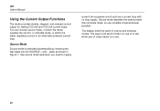
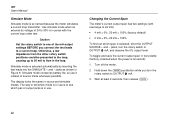
...use simulate mode whenever possible. 787 Users Manual Using the Current Output Functions The meter provides steady, stepped, and ramped current output for testing 0-20 mA and 4-20 mA current loops. The way to tell which mode is in use is to supply current into the SOURCE + and − jacks... as a current loop with no loop supply. Source mode depletes the battery faster than simulate mode, so use . 20 Source Mode Source mode is in source and simulate modes. Use source mode whenever you need to see which the ...
...use simulate mode whenever possible. 787 Users Manual Using the Current Output Functions The meter provides steady, stepped, and ramped current output for testing 0-20 mA and 4-20 mA current loops. The way to tell which mode is in use is to supply current into the SOURCE + and − jacks... as a current loop with no loop supply. Source mode depletes the battery faster than simulate mode, so use . 20 Source Mode Source mode is in source and simulate modes. Use source mode whenever you need to see which the ...
FE 787 Users Manual
Page 25
Sourcing Current ee010f.eps 21 787 PROCESSMETER MIN MAX % STEP RANGE COARSE REL HOLD H FINE Hz mV V mA A OUTPUT mA V mA OFF OUTPUT 0-24mA SOURCE + SIMULATE + A mA COM V 0.44A (1A /30 sec) FUSED 30mA FUSED CAT 1000V ProcessMeter Using the Current Output Functions 40 20 60 80 0 100 Figure 7.
Sourcing Current ee010f.eps 21 787 PROCESSMETER MIN MAX % STEP RANGE COARSE REL HOLD H FINE Hz mV V mA A OUTPUT mA V mA OFF OUTPUT 0-24mA SOURCE + SIMULATE + A mA COM V 0.44A (1A /30 sec) FUSED 30mA FUSED CAT 1000V ProcessMeter Using the Current Output Functions 40 20 60 80 0 100 Figure 7.
FE 787 Users Manual
Page 26
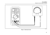
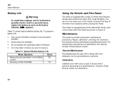
...use is to see which span is in use it instead of the mA output settings BEFORE you turn the rotary switch to one of source mode whenever possible. Changing the Current Span The meter's current output span has two settings (with the current loop under test. Hold ...mA. 3. Simulate mode is so named because the meter simulates a current loop transmitter. The display looks the same in the loop. Turn off ): 1. 787 Users Manual Simulate Mode Simulate mode is selected automatically by inserting the test leads into the SIMULATE + and − jacks as shown in Figure 8. Simulate...
...use is to see which span is in use it instead of the mA output settings BEFORE you turn the rotary switch to one of source mode whenever possible. Changing the Current Span The meter's current output span has two settings (with the current loop under test. Hold ...mA. 3. Simulate mode is so named because the meter simulates a current loop transmitter. The display looks the same in the loop. Turn off ): 1. 787 Users Manual Simulate Mode Simulate mode is selected automatically by inserting the test leads into the SIMULATE + and − jacks as shown in Figure 8. Simulate...

FE 787 Users Manual
Page 27
Simulating a Transmitter ee011f.eps 23 dc V Power Supply COM +24V 787 PROCESSMETER MIN MAX % STEP RANGE COARSE REL HOLD H FINE Hz mV V mA A OUTPUT mA V mA OFF OUTPUT 0-24mA SOURCE + SIMULATE + A mA COM V 0.44A (1A /30 sec) FUSED 30mA FUSED CAT 1000V ProcessMeter Using the Current Output Functions 40 20 60 80 0 100 Figure 8.
Simulating a Transmitter ee011f.eps 23 dc V Power Supply COM +24V 787 PROCESSMETER MIN MAX % STEP RANGE COARSE REL HOLD H FINE Hz mV V mA A OUTPUT mA V mA OFF OUTPUT 0-24mA SOURCE + SIMULATE + A mA COM V 0.44A (1A /30 sec) FUSED 30mA FUSED CAT 1000V ProcessMeter Using the Current Output Functions 40 20 60 80 0 100 Figure 8.
FE 787 Users Manual
Page 28
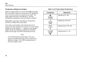
... current because the load resistance is too high or the loop supply voltage is low enough, the meter will resume sourcing. When the impedance between the SOURCE jacks is too low, dashes (-----) appear on the next page are available when the meter is in Table 8. ... Adjustment Adjusts up 0.1 mA Adjusts up 0.001 mA Adjusts down 0.001 mA Adjusts down 0.1 mA 24 787 Users Manual Producing a Steady mA Output When the rotary switch is producing a steady mA output. The meter begins sourcing or simulating 0%. Use the pushbuttons to the next multiple of 25%. Table 8. Select either...
... current because the load resistance is too high or the loop supply voltage is low enough, the meter will resume sourcing. When the impedance between the SOURCE jacks is too low, dashes (-----) appear on the next page are available when the meter is in Table 8. ... Adjustment Adjusts up 0.1 mA Adjusts up 0.001 mA Adjusts down 0.001 mA Adjusts down 0.1 mA 24 787 Users Manual Producing a Steady mA Output When the rotary switch is producing a steady mA output. The meter begins sourcing or simulating 0%. Use the pushbuttons to the next multiple of 25%. Table 8. Select either...
FE 787 Users Manual
Page 29
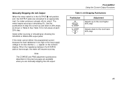
... simulating by choosing the SOURCE or SIMULATE output jacks. mA Stepping Pushbuttons Pushbutton X M % STEP % STEP T W Adjustment Adjusts up and down to... The COARSE and FINE adjustment pushbuttons described on the numeric display. ProcessMeter Using the Current Output Functions Table 9. The meter begins sourcing or simulating 0%. Use the pushbuttons to step the current up to an appropriate load, the meter produces a steady mA dc ...Stepping the mA Output When the rotary switch is in Table 9. When the impedance between the SOURCE jacks is low enough, the meter will resume...
... simulating by choosing the SOURCE or SIMULATE output jacks. mA Stepping Pushbuttons Pushbutton X M % STEP % STEP T W Adjustment Adjusts up and down to... The COARSE and FINE adjustment pushbuttons described on the numeric display. ProcessMeter Using the Current Output Functions Table 9. The meter begins sourcing or simulating 0%. Use the pushbuttons to step the current up to an appropriate load, the meter produces a steady mA dc ...Stepping the mA Output When the rotary switch is in Table 9. When the impedance between the SOURCE jacks is low enough, the meter will resume...

FE 787 Users Manual
Page 30
... transmitter, while your choice of the transmitter. Then you can freeze the ramp simply by choosing the SOURCE or SIMULATE jacks. Press the BLUE pushbutton to cycle through the three waveforms. Note At any time...- 0% 15-second smooth ramp N 0% - 100% - 0% Stair-step ramp in Table 10. Steps are not adjustable. Select either sourcing or simulating by moving the rotary switch to make adjustments. 26 The ramp times are listed in 25% steps, pausing 5 seconds at each... pushbuttons to the [ mA position. 787 Users Manual Step 0% 25% 50% 75% 100% 125% 120% Table 10.
... transmitter, while your choice of the transmitter. Then you can freeze the ramp simply by choosing the SOURCE or SIMULATE jacks. Press the BLUE pushbutton to cycle through the three waveforms. Note At any time...- 0% 15-second smooth ramp N 0% - 100% - 0% Stair-step ramp in Table 10. Steps are not adjustable. Select either sourcing or simulating by moving the rotary switch to make adjustments. 26 The ramp times are listed in 25% steps, pausing 5 seconds at each... pushbuttons to the [ mA position. 787 Users Manual Step 0% 25% 50% 75% 100% 125% 120% Table 10.
FE 787 Users Manual
Page 32
...procedures not described in Figure 9. Contact a Fluke Service Center for instructions. 28 The holster ... face of the meter from rough handling. Table 12. Some uses of sourcing when possible. • Avoid using it performs according to possible electric shock... it . You can turn the meter over in this manual, contact a Fluke Service Center. Repair, calibration, servicing not covered in the holster to ensure that... Typical Alkaline Battery Life Meter Operation Measuring any parameter or simulating current Sourcing 12 mA into 500Ω Hours 80 12 Using the Holster and...
...procedures not described in Figure 9. Contact a Fluke Service Center for instructions. 28 The holster ... face of the meter from rough handling. Table 12. Some uses of sourcing when possible. • Avoid using it performs according to possible electric shock... it . You can turn the meter over in this manual, contact a Fluke Service Center. Repair, calibration, servicing not covered in the holster to ensure that... Typical Alkaline Battery Life Meter Operation Measuring any parameter or simulating current Sourcing 12 mA into 500Ω Hours 80 12 Using the Holster and...
FE 787 Users Manual
Page 45
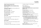
Diode Test and Continuity Test Diode test indication: display voltage drop: 0.2 mA nominal test current at 0.6V: 2.4V full scale, accuracy ±(2% + 1 count) Continuity test indication: continuous audible tone for test resistance
Diode Test and Continuity Test Diode test indication: display voltage drop: 0.2 mA nominal test current at 0.6V: 2.4V full scale, accuracy ±(2% + 1 count) Continuity test indication: continuous audible tone for test resistance

FE 787 Users Manual
Page 47
Battery Replacement, 30 Buttons, 12 -C- Calibrating the meter, 28 Compensating for test lead resistance, 19 Composite Signals, 17 Index Current output Compliance, 24 Load impedance, 24 Ramping, auto, 26 Simulating a transmitter, 22 Sourcing, 20 Span (4-20 mA or 0-20 mA), 22 Steady, 24 Stepping, auto, 26 Stepping, manually, 25 With external loop supply, 22 -D- Auto Ramping, 17, 26 Ranging, 17 Stepping, 17 -B- Diodes, testing, 18 Display, 15 43 -A-
Battery Replacement, 30 Buttons, 12 -C- Calibrating the meter, 28 Compensating for test lead resistance, 19 Composite Signals, 17 Index Current output Compliance, 24 Load impedance, 24 Ramping, auto, 26 Simulating a transmitter, 22 Sourcing, 20 Span (4-20 mA or 0-20 mA), 22 Steady, 24 Stepping, auto, 26 Stepping, manually, 25 With external loop supply, 22 -D- Auto Ramping, 17, 26 Ranging, 17 Stepping, 17 -B- Diodes, testing, 18 Display, 15 43 -A-