
FE 53 & 54 II Users Manual
Page 1
Printed in USA All product names are trademarks of their respective companies. ® 53 & 54 Series II Thermometer Users Manual September 1999 Rev.1, 6/01 © 1999-2001 Fluke Corporation, All rights reserved.
Printed in USA All product names are trademarks of their respective companies. ® 53 & 54 Series II Thermometer Users Manual September 1999 Rev.1, 6/01 © 1999-2001 Fluke Corporation, All rights reserved.

FE 53 & 54 II Users Manual
Page 4
53 & 54 Series II Users Manual Displaying Temperatures 14 Holding the Displayed Temperatures 14 Viewing the MIN, MAX, and AVG Readings 14 Using the Offset to Adjust for Probe Errors 15 ... and Holster 19 Calibration ...19 Specifications ...19 Environmental...19 General...20 80 PK-1 Thermocouple (supplied with thermometer 20 Electrical...20 Replacement Parts and Accessories 21 ii
53 & 54 Series II Users Manual Displaying Temperatures 14 Holding the Displayed Temperatures 14 Viewing the MIN, MAX, and AVG Readings 14 Using the Offset to Adjust for Probe Errors 15 ... and Holster 19 Calibration ...19 Specifications ...19 Environmental...19 General...20 80 PK-1 Thermocouple (supplied with thermometer 20 Electrical...20 Replacement Parts and Accessories 21 ii

FE 53 & 54 II Users Manual
Page 5
53 & 54 Series II Safety Information The Fluke Model 53 and Model 54 Thermometers ("the thermometer") are microprocessor-based, digital thermometers designed to safety information in Table 1 and the meter symbols in Table 2. Box 9090 Everett, WA 98206-9090 USA Fluke Europe B.V. Use the thermometer only as temperature sensors. Refer to use ... locate the nearest Fluke distributor or Service Center, call: 1-888-99-FLUKE (1-888-993-5853) in USA 1-800-36-FLUKE (1-800-363-5853) in Canada +31-402-678-200 in Europe +81-3-3434-0181 in Japan +65-738-5655 in this manual. Otherwise, the ...
53 & 54 Series II Safety Information The Fluke Model 53 and Model 54 Thermometers ("the thermometer") are microprocessor-based, digital thermometers designed to safety information in Table 1 and the meter symbols in Table 2. Box 9090 Everett, WA 98206-9090 USA Fluke Europe B.V. Use the thermometer only as temperature sensors. Refer to use ... locate the nearest Fluke distributor or Service Center, call: 1-888-99-FLUKE (1-888-993-5853) in USA 1-800-36-FLUKE (1-800-363-5853) in Canada +31-402-678-200 in Europe +81-3-3434-0181 in Japan +65-738-5655 in this manual. Otherwise, the ...
FE 53 & 54 II Users Manual
Page 6
... the case. • Replace the batteries as soon as marked on the thermometer, between the thermocouple(s), or between any thermocouple and earth ground. 2 53 & 54 Series II Users Manual Table 1. The possibility of false readings can lead to the insulation around explosive gas, vapor, or dust. • Do not apply more than the...
... the case. • Replace the batteries as soon as marked on the thermometer, between the thermocouple(s), or between any thermocouple and earth ground. 2 53 & 54 Series II Users Manual Table 1. The possibility of false readings can lead to the insulation around explosive gas, vapor, or dust. • Do not apply more than the...

FE 53 & 54 II Users Manual
Page 8
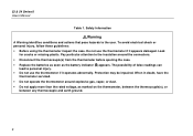
53 & 54 Series II Users Manual Table 2. P Complies with relevant Canadian Standards Association directives. Complies with European Union directives. To become familiar with the thermometer, study the following sections. 4 M Battery. Getting Started Everything in this Users Manual applies both to the manual for information about this feature. Then read the following : • Figure 1 and Table 3 describe...
53 & 54 Series II Users Manual Table 2. P Complies with relevant Canadian Standards Association directives. Complies with European Union directives. To become familiar with the thermometer, study the following sections. 4 M Battery. Getting Started Everything in this Users Manual applies both to the manual for information about this feature. Then read the following : • Figure 1 and Table 3 describe...

FE 53 & 54 II Users Manual
Page 10
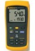
... not change. C A shift function is in progress. Model 53: T1 reading. Model 54: T1 or T2 reading. D Readings are displayed. Replace the batteries. K The thermocouple type. E Setup is in SETUP. Model 54: T1, T2, or T1-T2 reading. J Secondary Display: MAX, MIN, AVG, MEMORY... has been set. L Time Display: 24-hour clock. Shows the INTERVAL length in progress. F Logged readings are being logged. 53 & 54 Series II Users Manual Display Elements 2 3 45 1 xx 6 7 12 11 Figure 2. Display Elements 8 9 10 aat02f.eps 6 Table 4. I The temperature units. G ...
... not change. C A shift function is in progress. Model 53: T1 reading. Model 54: T1 or T2 reading. D Readings are displayed. Replace the batteries. K The thermocouple type. E Setup is in SETUP. Model 54: T1, T2, or T1-T2 reading. J Secondary Display: MAX, MIN, AVG, MEMORY... has been set. L Time Display: 24-hour clock. Shows the INTERVAL length in progress. F Logged readings are being logged. 53 & 54 Series II Users Manual Display Elements 2 3 45 1 xx 6 7 12 11 Figure 2. Display Elements 8 9 10 aat02f.eps 6 Table 4. I The temperature units. G ...

FE 53 & 54 II Users Manual
Page 12
Press N to freeze or unfreeze the displayed readings. During manual logging, the thermometer stores a single set of logged readings in memory each time you want to change . Buttons (cont.) Press h to decrease the displayed ...to toggle showing the T1, T2, and T1-T2 (differential temperature measurement) in memory. Press r to increase the displayed setting. Model 54: Press T to test the display. Press r again to the Setup option you press J. 53 & 54 Series II Users Manual h T D K N E J r Table 5. Press h when turning on the display. Press N to scroll to stop logging....
Press N to freeze or unfreeze the displayed readings. During manual logging, the thermometer stores a single set of logged readings in memory each time you want to change . Buttons (cont.) Press h to decrease the displayed ...to toggle showing the T1, T2, and T1-T2 (differential temperature measurement) in memory. Press r to increase the displayed setting. Model 54: Press T to test the display. Press r again to the Setup option you press J. 53 & 54 Series II Users Manual h T D K N E J r Table 5. Press h when turning on the display. Press N to scroll to stop logging....

FE 53 & 54 II Users Manual
Page 14
Holding down K or N causes the number to display the logging interval choices. 3. 53 & 54 Series II Users Manual Changing the Logging Interval The logging interval determines how often the thermometer stores logged readings in memory. 1. See "Using Memory." Press E to change more quickly. ...
Holding down K or N causes the number to display the logging interval choices. 3. 53 & 54 Series II Users Manual Changing the Logging Interval The logging interval determines how often the thermometer stores logged readings in memory. 1. See "Using Memory." Press E to change more quickly. ...

FE 53 & 54 II Users Manual
Page 16
... logging modes. Press K or N until the display shows the correct hour (24-hour format), and then press E to store the time in memory. 53 & 54 Series II Users Manual Enabling or Disabling Sleep Mode The thermometer enters sleep mode if no button press occurs for 20 minutes. Setting the Time 1. Press K or N until...
... logging modes. Press K or N until the display shows the correct hour (24-hour format), and then press E to store the time in memory. 53 & 54 Series II Users Manual Enabling or Disabling Sleep Mode The thermometer enters sleep mode if no button press occurs for 20 minutes. Setting the Time 1. Press K or N until...

FE 53 & 54 II Users Manual
Page 18
... C to the measurement location. Press h again to step through the maximum (MAX), minimum (MIN), or the average (AVG) readings. Model 54: If only thermocouple T2 is connected, the T2 reading appears in the primary or secondary display. Press M to turn off the HOLD function. Model... MIN MAX mode. 14 Notes The display shows "- - - -" when a thermocouple is outside the thermocouple's valid range. 53 & 54 Series II Users Manual Displaying Temperatures 1. The temperature reading appears in the primary or secondary display. 3. Viewing the MIN, MAX, and AVG Readings 1. The elapsed...
... C to the measurement location. Press h again to step through the maximum (MAX), minimum (MIN), or the average (AVG) readings. Model 54: If only thermocouple T2 is connected, the T2 reading appears in the primary or secondary display. Press M to turn off the HOLD function. Model... MIN MAX mode. 14 Notes The display shows "- - - -" when a thermocouple is outside the thermocouple's valid range. 53 & 54 Series II Users Manual Displaying Temperatures 1. The temperature reading appears in the primary or secondary display. 3. Viewing the MIN, MAX, and AVG Readings 1. The elapsed...

FE 53 & 54 II Users Manual
Page 20
...r or using FlukeView Forms. The data entries are a time stamp, the T1 reading, and the T2 and T1-T2 readings (Model 54). You can only view initial conditions using FlukeView Forms. Temperature readings display 0.1 degree resolution in memory. 16 Press J to stop logging.... sets of temperature readings and one set of initial conditions when logging individual points manually. If you selected a manual logging interval, press J each thermocouple input. 53 & 54 Series II Users Manual Initial Conditions and Data Entries Logged readings include initial conditions and data entries. The...
...r or using FlukeView Forms. The data entries are a time stamp, the T1 reading, and the T2 and T1-T2 readings (Model 54). You can only view initial conditions using FlukeView Forms. Temperature readings display 0.1 degree resolution in memory. 16 Press J to stop logging.... sets of temperature readings and one set of initial conditions when logging individual points manually. If you selected a manual logging interval, press J each thermocouple input. 53 & 54 Series II Users Manual Initial Conditions and Data Entries Logged readings include initial conditions and data entries. The...

FE 53 & 54 II Users Manual
Page 22
... IR (infrared) serial connection. and was stored in memory. You can use these forms to the FlukeView Forms Installation Guide and FlukeView Help. 53 & 54 Series II Users Manual 3. FlukeView Forms places the logged readings into standard (default) or customized forms. The forms also display user comments. Maximum Reading aat04f.eps 4. Refer to...
... IR (infrared) serial connection. and was stored in memory. You can use these forms to the FlukeView Forms Installation Guide and FlukeView Help. 53 & 54 Series II Users Manual 3. FlukeView Forms places the logged readings into standard (default) or customized forms. The forms also display user comments. Maximum Reading aat04f.eps 4. Refer to...

FE 53 & 54 II Users Manual
Page 23
... to +140 oF) Humidity Non condensing Wipe with a damp sponge or soft rag. 53 & 54 Series II Maintenance Calibration To ensure that the thermometer performs to its accuracy specifications, Fluke recommends that you or follow the calibration procedure in the service manual listed in Table 1 before replacing the batteries. 1. To calibrate the thermometer, contact...
... to +140 oF) Humidity Non condensing Wipe with a damp sponge or soft rag. 53 & 54 Series II Maintenance Calibration To ensure that the thermometer performs to its accuracy specifications, Fluke recommends that you or follow the calibration procedure in the service manual listed in Table 1 before replacing the batteries. 1. To calibrate the thermometer, contact...

FE 53 & 54 II Users Manual
Page 24
...: −200 oC to +1300 oC (−328 oF to the level of OVERVOLTAGE CATEGORY I , Pollution Degree 2 per IEC1010-1* * Refers to +2372 oF) R- 53 & 54 Series II Users Manual General Weight 280 g (10 oz) Dimensions (without holster) 2.8 cm × 7.8 cm × 16.2 cm (1.1 in × 3 in × 6.4 in) Battery Certification 3 AA batteries P, s Safety...
...: −200 oC to +1300 oC (−328 oF to the level of OVERVOLTAGE CATEGORY I , Pollution Degree 2 per IEC1010-1* * Refers to +2372 oF) R- 53 & 54 Series II Users Manual General Weight 280 g (10 oz) Dimensions (without holster) 2.8 cm × 7.8 cm × 16.2 cm (1.1 in × 3 in × 6.4 in) Battery Certification 3 AA batteries P, s Safety...

FE 53 & 54 II Users Manual
Page 25
... add 0.04 % of reading for a period of 1 year. The above specifications do not include thermocouple error. 53 & 54 Series II Replacement Parts and Accessories Replacement Parts and Accessories Accessory Part Number Holster and Flex Stand™ Assembly 1272438 AA NEDA 15A IEC ...LR6 batteries 376756 80PK-1 K-Type Bead Thermocouple 773135 CD-ROM 1276106 Service Manual 1276123 21 and S-type: 0.4 oC (0.7 oF)] ±...
... add 0.04 % of reading for a period of 1 year. The above specifications do not include thermocouple error. 53 & 54 Series II Replacement Parts and Accessories Replacement Parts and Accessories Accessory Part Number Holster and Flex Stand™ Assembly 1272438 AA NEDA 15A IEC ...LR6 batteries 376756 80PK-1 K-Type Bead Thermocouple 773135 CD-ROM 1276106 Service Manual 1276123 21 and S-type: 0.4 oC (0.7 oF)] ±...

FE 53 & 54 II Users Manual
Page 26
53 & 54 Series II Users Manual 22
53 & 54 Series II Users Manual 22


