
FE 192,196,199 C Users Manual
Page 15
Powering the Test Tool Follow the procedure (steps 1 through 3) in its last setup configuration. Powering the Test Tool 7 Turn the test tool on with the on using battery power. The introduction does not cover all of the capabilities ...
Powering the Test Tool Follow the procedure (steps 1 through 3) in its last setup configuration. Powering the Test Tool 7 Turn the test tool on with the on using battery power. The introduction does not cover all of the capabilities ...
FE 192,196,199 C Users Manual
Page 20
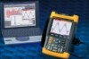
... Auto Set Use the light-gray RANGE, TIME and MOVE keys at the top right of the waveform manually. 12 If the signal changes, the setup is automatically adjusted to change the view of the screen. The bottom line shows the range, the time base, and the trigger information. icon ( ) ...at the top right of the keypad to maintain the best display result. Fluke 192B - 196B/C - 199B/C Users Manual Displaying an Unknown Signal with Connect-and-View™ The Connect-and-View feature lets the test tool display complex...
... Auto Set Use the light-gray RANGE, TIME and MOVE keys at the top right of the waveform manually. 12 If the signal changes, the setup is automatically adjusted to change the view of the screen. The bottom line shows the range, the time base, and the trigger information. icon ( ) ...at the top right of the keypad to maintain the best display result. Fluke 192B - 196B/C - 199B/C Users Manual Displaying an Unknown Signal with Connect-and-View™ The Connect-and-View feature lets the test tool display complex...
FE 192,196,199 C Users Manual
Page 32
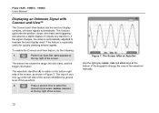
... deleted in the previous section "Comparing Waveforms" 2 From the Pass Fail Testing: menu select Store Fail : each scope screen with Associated Setups. Chapter 4 provides information on the display is a waveform envelope. Fluke 192B - 196B/C - 199B/C Users Manual 7 Store the momentary waveform and display it as a test template for the actual waveform. To...
... deleted in the previous section "Comparing Waveforms" 2 From the Pass Fail Testing: menu select Store Fail : each scope screen with Associated Setups. Chapter 4 provides information on the display is a waveform envelope. Fluke 192B - 196B/C - 199B/C Users Manual 7 Store the momentary waveform and display it as a test template for the actual waveform. To...
FE 192,196,199 C Users Manual
Page 37
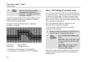
Ensure that the red and black probe connectors 5 correspond to be measured. Open the Current Probe submenu. 29 Measurement Setup Open the Measurement menu. Highlight A ac.... Meter mode has the advantage of two waveforms being displayed while you are using. i400, optional) from the 4-mm ...
Ensure that the red and black probe connectors 5 correspond to be measured. Open the Current Probe submenu. 29 Measurement Setup Open the Measurement menu. Highlight A ac.... Meter mode has the advantage of two waveforms being displayed while you are using. i400, optional) from the 4-mm ...
FE 192,196,199 C Users Manual
Page 70
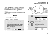
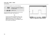
Use the REPLAY key to adjust the pulse width. 8 Select 5 ms. All narrow positive pulses shorter than 5 ms are now displayed on Narrow Glitches 62 Fluke 192B - 196B/C - 199B/C Users Manual To set the pulse width to 5 ms, do the following: 7 Enable the arrow keys to look at all triggered screens in the replay memory. Triggering on the screen. (See Figure 33.) Tip The test tool stores all the stored glitches. Figure 33. For example, if you setup your triggering for glitches, you can capture 100 glitches with time stamps.
Use the REPLAY key to adjust the pulse width. 8 Select 5 ms. All narrow positive pulses shorter than 5 ms are now displayed on Narrow Glitches 62 Fluke 192B - 196B/C - 199B/C Users Manual To set the pulse width to 5 ms, do the following: 7 Enable the arrow keys to look at all triggered screens in the replay memory. Triggering on the screen. (See Figure 33.) Tip The test tool stores all the stored glitches. Figure 33. For example, if you setup your triggering for glitches, you can capture 100 glitches with time stamps.

FE 192,196,199 C Users Manual
Page 73
... and Recalling You can be used in the three main modes: Scope, Meter, or Recorder. The test tool has 10 screen and setup memories and 2 record and setup memories. • Recall screens and recordings to analyze or print the screen image at the end of the test tool that can :... memory, and recall them again from memory. You will find information on printer and computer communication at a later date. • Recall a setup to continue a measurement with the recalled operating configuration. 65 Chapter 6 Using Memory, PC and Printer About this Chapter This chapter provides a step...
... and Recalling You can be used in the three main modes: Scope, Meter, or Recorder. The test tool has 10 screen and setup memories and 2 record and setup memories. • Recall screens and recordings to analyze or print the screen image at the end of the test tool that can :... memory, and recall them again from memory. You will find information on printer and computer communication at a later date. • Recall a setup to continue a measurement with the recalled operating configuration. 65 Chapter 6 Using Memory, PC and Printer About this Chapter This chapter provides a step...
FE 192,196,199 C Users Manual
Page 74
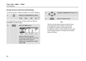
...locations store more than what is saved. From this point the screen is frozen until you can save a screen in a single record+setup memory location. 66 In TrendPlot or scope record mode the full recording is just visible on the screen. Observe that free memory locations are... by an open square (‡). In scope mode you hide the SAVE/PRINT key labels again. 2 Open the Save menu. Fluke 192B - 196B/C - 199B/C Users Manual Saving Screens with Associated Setups To save all 100 replay screens in memory location 10, do the following: 1 Display the SAVE/PRINT key labels.
...locations store more than what is saved. From this point the screen is frozen until you can save a screen in a single record+setup memory location. 66 In TrendPlot or scope record mode the full recording is just visible on the screen. Observe that free memory locations are... by an open square (‡). In scope mode you hide the SAVE/PRINT key labels again. 2 Open the Save menu. Fluke 192B - 196B/C - 199B/C Users Manual Saving Screens with Associated Setups To save all 100 replay screens in memory location 10, do the following: 1 Display the SAVE/PRINT key labels.
FE 192,196,199 C Users Manual
Page 75
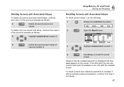
... Observe that the recalled waveform is displayed and that HOLD appears on the screen. Deleting Screens with Associated Setups To recall screen+setup 1, do the following: 1 Display the SAVE/PRINT key labels. 2 Open the Recall menu. 4 Delete the saved screen...6 Using Memory, PC and Printer Saving and Recalling Recalling Screens with Associated Setups To delete all screens and associated setups, continue from step 3 as follows: 3 Delete all saved screens and setups. To delete only one screen and setup, continue from step 2 of the previous example as follows: 67 To recall...
... Observe that the recalled waveform is displayed and that HOLD appears on the screen. Deleting Screens with Associated Setups To recall screen+setup 1, do the following: 1 Display the SAVE/PRINT key labels. 2 Open the Recall menu. 4 Delete the saved screen...6 Using Memory, PC and Printer Saving and Recalling Recalling Screens with Associated Setups To delete all screens and associated setups, continue from step 3 as follows: 3 Delete all saved screens and setups. To delete only one screen and setup, continue from step 2 of the previous example as follows: 67 To recall...
FE 192,196,199 C Users Manual
Page 76
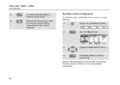
From this point you continue in the new operating configuration. 68 Both, the reference screen and the measurement screen will be displayed. Observe that RUN appears at the top right of the screen. Recalling a Setup Configuration To recall the setup configuration from memory 1, do the following: 1 Display the SAVE/PRINT key labels. 2 Open the Recall menu. 3 Highlight SCREEN+SETUP location 1. 4 Use RECALL SETUP to recall the saved screen. 5 Resume the measurement. Fluke 192B - 196B/C - 199B/C Users Manual 4 Use RECALL FOR REFERENCE to recall the saved setup.
From this point you continue in the new operating configuration. 68 Both, the reference screen and the measurement screen will be displayed. Observe that RUN appears at the top right of the screen. Recalling a Setup Configuration To recall the setup configuration from memory 1, do the following: 1 Display the SAVE/PRINT key labels. 2 Open the Recall menu. 3 Highlight SCREEN+SETUP location 1. 4 Use RECALL SETUP to recall the saved screen. 5 Resume the measurement. Fluke 192B - 196B/C - 199B/C Users Manual 4 Use RECALL FOR REFERENCE to recall the saved setup.
FE 192,196,199 C Users Manual
Page 78
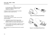
Fluke 192B - 196B/C - 199B/C Users Manual Note For information about installing and using the FlukeView ScopeMeter software, see the SW90W Users Manual. Connecting a Parallel Printer A Software & ....) z The Print Adapter Cable (PAC91, optional) to connect a parallel printer to the OPTICAL PORT of the test tool. (See Figure 37.) Before printing, you must setup the test tool for a specific printer. 70 Figure 36. Connecting a Serial Printer Figure 37.
Fluke 192B - 196B/C - 199B/C Users Manual Note For information about installing and using the FlukeView ScopeMeter software, see the SW90W Users Manual. Connecting a Parallel Printer A Software & ....) z The Print Adapter Cable (PAC91, optional) to connect a parallel printer to the OPTICAL PORT of the test tool. (See Figure 37.) Before printing, you must setup the test tool for a specific printer. 70 Figure 36. Connecting a Serial Printer Figure 37.

FE 192,196,199 C Users Manual
Page 79
... bottom of the screen indicating that came with a 9600 baud rate: 1 Display the USER OPTIONS key labels. 2 Open the User Options menu. 3 Open the Printer Setup submenu. 4 Select Postscript and jump to Baud Rate. 5 Select a baud rate of 9600 and return to normal mode. 6 Using Memory, PC and Printer Documenting Screens...
... bottom of the screen indicating that came with a 9600 baud rate: 1 Display the USER OPTIONS key labels. 2 Open the User Options menu. 3 Open the Printer Setup submenu. 4 Select Postscript and jump to Baud Rate. 5 Select a baud rate of 9600 and return to normal mode. 6 Using Memory, PC and Printer Documenting Screens...
FE 192,196,199 C Users Manual
Page 114
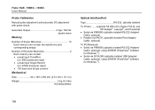
... Cable, optional), using SW90W (FlukeView® software for Windows ®). • Serial via PAC91 (optically isolated Print Adapter Cable, optional). Fluke 192B - 196B/C - 199B/C Users Manual Probe Calibration Manual pulse adjustment and automatic DC adjustment with probe check. Generator Output 3 Vpp /... 500 Hz square wave Memory Number of Scope Memories 10 Each memory can contain two waveforms plus corresponding setups Number of Recorder Memories 2 Each memory can contain: • a dual input TrendPlot (2 x 9000 points per input) • a dual...
... Cable, optional), using SW90W (FlukeView® software for Windows ®). • Serial via PAC91 (optically isolated Print Adapter Cable, optional). Fluke 192B - 196B/C - 199B/C Users Manual Probe Calibration Manual pulse adjustment and automatic DC adjustment with probe check. Generator Output 3 Vpp /... 500 Hz square wave Memory Number of Scope Memories 10 Each memory can contain two waveforms plus corresponding setups Number of Recorder Memories 2 Each memory can contain: • a dual input TrendPlot (2 x 9000 points per input) • a dual...

FE 192,196,199 C Users Manual
Page 121
... Probe Calibration, 86, 106 Pulse Trigger, 61 Pulse Width, 100 Pulse Width Trigger, 98 -R- Readings, 13 Recalibrating, 88 Recalling Screens, 67 Recalling Setups, 68 Record Length, 97 Record+Setup Memory, 66 Recorder, 104 Recorder Options, 36 Index (continued) Recording Waveforms, 37 Refreshing Batteries, 88 Relative Measurements, 32 Replaceable Parts, 88 Replacement Set...
... Probe Calibration, 86, 106 Pulse Trigger, 61 Pulse Width, 100 Pulse Width Trigger, 98 -R- Readings, 13 Recalibrating, 88 Recalling Screens, 67 Recalling Setups, 68 Record Length, 97 Record+Setup Memory, 66 Recorder, 104 Recorder Options, 36 Index (continued) Recording Waveforms, 37 Refreshing Batteries, 88 Relative Measurements, 32 Replaceable Parts, 88 Replacement Set...