Product Manual
Page 4
1586A Users Manual Digital I/O...1-22 Totalizer...1-22 Trigger ...1-22 Alarm Output 1-22 1586-2588 DAQ-STAQ Input Module Specifications 1-22 General ...1-22 1586-2586 High-Capacity Input Module Specifications 1-22 General ...1-22 2 Initial Setup and Configuration 2-1 Introduction...2-3 Set the Regional Voltage 2-3 Connect to Mains Power 2-4 Set the Handle Position 2-5 Power On and Standby 2-6 Warm-Up the Product 2-7 Configure the Product 2-7 Input Module and Relay Card Installation 2-8 Install a DAQ-STAQ Multiplexer Connection Module...
1586A Users Manual Digital I/O...1-22 Totalizer...1-22 Trigger ...1-22 Alarm Output 1-22 1586-2588 DAQ-STAQ Input Module Specifications 1-22 General ...1-22 1586-2586 High-Capacity Input Module Specifications 1-22 General ...1-22 2 Initial Setup and Configuration 2-1 Introduction...2-3 Set the Regional Voltage 2-3 Connect to Mains Power 2-4 Set the Handle Position 2-5 Power On and Standby 2-6 Warm-Up the Product 2-7 Configure the Product 2-7 Input Module and Relay Card Installation 2-8 Install a DAQ-STAQ Multiplexer Connection Module...
Product Manual
Page 5
... How to Read the Data CSV File 4-24 5 Measure/DMM Operation 5-1 Introduction...5-3 About the Measure Function 5-3 About the DMM Function 5-3 Input Type Selection and Range Adjustment 5-4 Relative Measurements 5-4 Graph the Measurements 5-5 Measurement Statistics 5-6 6 Maintenance and Care 6-1 Introduction...6-3 Clean the Product 6-3 Replace the Fuse 6-3 Memory Reset and Factory Reset 6-4 User-Replaceable Parts and Accessories 6-5 7 Error Messages and Troubleshooting 7-1 Introduction...7-3 iii MyFlukeStore Shop for Fluke products online at: www. .com...
... How to Read the Data CSV File 4-24 5 Measure/DMM Operation 5-1 Introduction...5-3 About the Measure Function 5-3 About the DMM Function 5-3 Input Type Selection and Range Adjustment 5-4 Relative Measurements 5-4 Graph the Measurements 5-5 Measurement Statistics 5-6 6 Maintenance and Care 6-1 Introduction...6-3 Clean the Product 6-3 Replace the Fuse 6-3 Memory Reset and Factory Reset 6-4 User-Replaceable Parts and Accessories 6-5 7 Error Messages and Troubleshooting 7-1 Introduction...7-3 iii MyFlukeStore Shop for Fluke products online at: www. .com...
Product Manual
Page 7
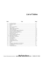
... User-Replaceable Parts and Accessories 6-5 7-1. Resistance Channel Configuration 3-20 3-6. Instrument Setup Menu 2-7 3-1. Totalizer Channel Configuration 3-26 3-10. Scan Sample Rates 4-9 4-3. Types of the Memory Clear Functions 6-4 6-3. Scan Data Memory Usage 4-20 5-1. Channel Types and Numbers 3-10 3-3. Automated Test Setup 4-17 4-5. Fuses...6-3 6-2. Comparison of Inputs...3-8 3-2. PRT Channel Setup 3-23 3-9. Math Channel Configuration 3-29 4-1. List of Tables Table Title Page 1-1. Troublehooting Chart 7-20 v MyFlukeStore Shop for Fluke...
... User-Replaceable Parts and Accessories 6-5 7-1. Resistance Channel Configuration 3-20 3-6. Instrument Setup Menu 2-7 3-1. Totalizer Channel Configuration 3-26 3-10. Scan Sample Rates 4-9 4-3. Types of the Memory Clear Functions 6-4 6-3. Scan Data Memory Usage 4-20 5-1. Channel Types and Numbers 3-10 3-3. Automated Test Setup 4-17 4-5. Fuses...6-3 6-2. Comparison of Inputs...3-8 3-2. PRT Channel Setup 3-23 3-9. Math Channel Configuration 3-29 4-1. List of Tables Table Title Page 1-1. Troublehooting Chart 7-20 v MyFlukeStore Shop for Fluke...
Product Manual
Page 8
... Temperature Control Source 4-16 4-8. List of a Scan Sweep 4-6 4-3. Screen Capture ...1-11 2-1. Main Power Switch and Standby Key 2-6 2-5. Channel Status Indicators 3-13 3-7. Zero Function ...3-15 3-8. Graph Feature ...4-14 4-6. Scan Data File Name Convention 4-21 4-9. DAQ-STAQ Multiplexer Installation 2-12 3-1. 2-Wire, 3-Wire, and 4-Wire Input Module Connections 3-3 3-2. 2-Wire, 3-Wire, and 4-Wire Multiplexer Connections 3-4 3-3. 3-Wire and 4-Wire Channel Reservation 3-7 3-4. Test Setup Menu Example 4-7 4-4. Fuse Replacement 6-4 vii MyFlukeStore Shop for Fluke...
... Temperature Control Source 4-16 4-8. List of a Scan Sweep 4-6 4-3. Screen Capture ...1-11 2-1. Main Power Switch and Standby Key 2-6 2-5. Channel Status Indicators 3-13 3-7. Zero Function ...3-15 3-8. Graph Feature ...4-14 4-6. Scan Data File Name Convention 4-21 4-9. DAQ-STAQ Multiplexer Installation 2-12 3-1. 2-Wire, 3-Wire, and 4-Wire Input Module Connections 3-3 3-2. 2-Wire, 3-Wire, and 4-Wire Multiplexer Connections 3-4 3-3. 3-Wire and 4-Wire Channel Reservation 3-7 3-4. Test Setup Menu Example 4-7 4-4. Fuse Replacement 6-4 vii MyFlukeStore Shop for Fluke...
Product Manual
Page 11
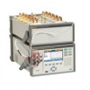
... Fluke Calibration 1586A SUPER-DAQ Precision Temperature Scanner (the Product or Instrument) is a 45 analog channel bench-top measurement instrument that can be included in a spreadsheet format along with a variety of -change. With the Graph feature, channel measurement data for up to graph and see Table 1-1). 1 Product Overview and Specifications Introduction Introduction This chapter supplies information about the Product, the manual set, safety information...
... Fluke Calibration 1586A SUPER-DAQ Precision Temperature Scanner (the Product or Instrument) is a 45 analog channel bench-top measurement instrument that can be included in a spreadsheet format along with a variety of -change. With the Graph feature, channel measurement data for up to graph and see Table 1-1). 1 Product Overview and Specifications Introduction Introduction This chapter supplies information about the Product, the manual set, safety information...
Product Manual
Page 12
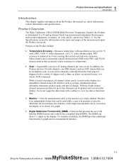
.... • Remote Operation - When the DIO channel is included in the scan list, the value of this port is recorded in the scan data record on the rear of data and channel setup files directly to a PC with remote SCPI commands from the rear-panel alarm output for Fluke products online at the rear of the unit with a value range of external devices. • Digital I/O (DIO) - Counter increment is read. • Totalizer - Remotely operate the...
.... • Remote Operation - When the DIO channel is included in the scan list, the value of this port is recorded in the scan data record on the rear of data and channel setup files directly to a PC with remote SCPI commands from the rear-panel alarm output for Fluke products online at the rear of the unit with a value range of external devices. • Digital I/O (DIO) - Counter increment is read. • Totalizer - Remotely operate the...
Product Manual
Page 14
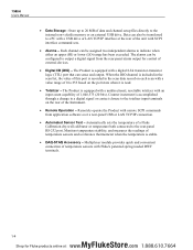
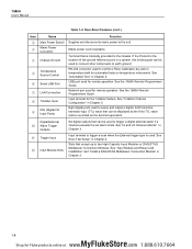
... when a channel is flashing. Front-Panel USB Port USB port to ON, it is logged. This date and time is used for Fluke products online at: www. .com 1.888.610.7664 See "Input Module and Relay Card Installation" in the Instrument Setup menu. When a channel is set to as "active". Menu Name Name of the menu. Hazardous Voltage Warns the user of a single channel. The Scan function samples...
... when a channel is flashing. Front-Panel USB Port USB port to ON, it is logged. This date and time is used for Fluke products online at: www. .com 1.888.610.7664 See "Input Module and Relay Card Installation" in the Instrument Setup menu. When a channel is set to as "active". Menu Name Name of the menu. Hazardous Voltage Warns the user of a single channel. The Scan function samples...
Product Manual
Page 15
... the Product is powered on either the internal memory or USB drive. Push and hold the LOCK key to lock the front panel to prevent changes and UNLOCK to recording scan data, measurements made with the front-panel inputs. See "Configure the Product" in Chapter 2. 1-7 MyFlukeStore Shop for instructions on the top of the display. Channel Setup is the default menu that lets the user quickly configure and...
... the Product is powered on either the internal memory or USB drive. Push and hold the LOCK key to lock the front panel to prevent changes and UNLOCK to recording scan data, measurements made with the front-panel inputs. See "Configure the Product" in Chapter 2. 1-7 MyFlukeStore Shop for instructions on the top of the display. Channel Setup is the default menu that lets the user quickly configure and...
Product Manual
Page 16
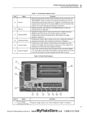
... temperature instruments. RS-232 connector used to trigger a scan when the External trigger type is internally grounded to trigger a digital external alarm if a channel exceeds the set alarm limits. 1586A Users Manual Table 1-2. Eight digital ports used to earth ground. See "HI and LO Channel Alarms" in a system, this binding post can be recorded as the 8-bit TTL value and be used to connect other instruments to control a Fluke Calibration dry-well or temperature...
... temperature instruments. RS-232 connector used to trigger a scan when the External trigger type is internally grounded to trigger a digital external alarm if a channel exceeds the set alarm limits. 1586A Users Manual Table 1-2. Eight digital ports used to earth ground. See "HI and LO Channel Alarms" in a system, this binding post can be recorded as the 8-bit TTL value and be used to connect other instruments to control a Fluke Calibration dry-well or temperature...
Product Manual
Page 17
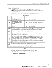
... and Specifications Safety Information Safety Information A Warning identifies conditions and procedures that are included because the test leads supplied with the WEEE Directive (2002/96/EC) marking requirements. Product Category: With reference to the user. The affixed label indicates that you use the Product. • Carefully read all instructions. 1-9 MyFlukeStore Shop for a list of the building's low-voltage MAINS installation...
... and Specifications Safety Information Safety Information A Warning identifies conditions and procedures that are included because the test leads supplied with the WEEE Directive (2002/96/EC) marking requirements. Product Category: With reference to the user. The affixed label indicates that you use the Product. • Carefully read all instructions. 1-9 MyFlukeStore Shop for a list of the building's low-voltage MAINS installation...

Product Manual
Page 20
... time use. • Chapter 3 supplies instructions on how to wire inputs to the Input Module then configure the associated channel. • Chapter 4 supplies information and instructions on how to do a scan, monitor a channel, and record measurement data. • Chapter 5 supplies instructions on how to operate the DMM function of the Product. • Chapter 7 supplies information on how to remotely operate the Product. The Programmers Guide alphabetically lists all commands and provides example code for Fluke products online...
... time use. • Chapter 3 supplies instructions on how to wire inputs to the Input Module then configure the associated channel. • Chapter 4 supplies information and instructions on how to do a scan, monitor a channel, and record measurement data. • Chapter 5 supplies instructions on how to operate the DMM function of the Product. • Chapter 7 supplies information on how to remotely operate the Product. The Programmers Guide alphabetically lists all commands and provides example code for Fluke products online...
Product Manual
Page 37
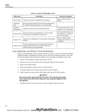
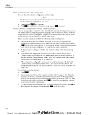
... and User profile passwords. See "Automatic Power Loss Scan Resume" in this chapter for Fluke products online at least one slot preconfigured with the name, serial number, and calibration date of the relay card are properly aligned in the slot guides. 7. Input Module and Relay Card Installation Before an Input Module can be installed. Use the procedure below and refer to Figure 2-6 as necessary to automatically turn on...
... and User profile passwords. See "Automatic Power Loss Scan Resume" in this chapter for Fluke products online at least one slot preconfigured with the name, serial number, and calibration date of the relay card are properly aligned in the slot guides. 7. Input Module and Relay Card Installation Before an Input Module can be installed. Use the procedure below and refer to Figure 2-6 as necessary to automatically turn on...
Product Manual
Page 44
... Introduction...3-3 Input Wiring...3-3 The 1586-2586 High Capacity Input Module 3-3 The 1586-2588 DAQ-STAQ Multiplexer Connector Module 3-4 Wiring Safety and Considerations 3-5 3-Wire and 4-Wire Sense Input Configuration 3-6 Input Types and Wiring Diagrams 3-7 Input Wiring Instructions 3-8 Channel Configuration 3-10 About Channel Numbers 3-10 Basic Channel Operations 3-12 Open the Channel Setup Menu 3-12 Set Channels to ON or OFF 3-13 Verify a Channel 3-14 Zero a Channel 3-14 Copy a Channel 3-15 Save or Load a Channel Configuration (Setup File 3-16 Reset the Channel and...
... Introduction...3-3 Input Wiring...3-3 The 1586-2586 High Capacity Input Module 3-3 The 1586-2588 DAQ-STAQ Multiplexer Connector Module 3-4 Wiring Safety and Considerations 3-5 3-Wire and 4-Wire Sense Input Configuration 3-6 Input Types and Wiring Diagrams 3-7 Input Wiring Instructions 3-8 Channel Configuration 3-10 About Channel Numbers 3-10 Basic Channel Operations 3-12 Open the Channel Setup Menu 3-12 Set Channels to ON or OFF 3-13 Verify a Channel 3-14 Zero a Channel 3-14 Copy a Channel 3-15 Save or Load a Channel Configuration (Setup File 3-16 Reset the Channel and...
Product Manual
Page 55
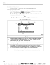
... shows in the channel list. 3-12 MyFlukeStore Shop for Fluke products online at: www. .com 1.888.610.7664 1586A Users Manual Basic Channel Operations Use the instructions in this section to the left of available channels. To quickly move up tests. Open the Channel Setup Menu The Channel Setup menu lets the user manage channels, verify inputs, and also set up and down the list of channels, use the and arrow keys. When a slot...
... shows in the channel list. 3-12 MyFlukeStore Shop for Fluke products online at: www. .com 1.888.610.7664 1586A Users Manual Basic Channel Operations Use the instructions in this section to the left of available channels. To quickly move up tests. Open the Channel Setup Menu The Channel Setup menu lets the user manage channels, verify inputs, and also set up and down the list of channels, use the and arrow keys. When a slot...
Product Manual
Page 61
... Channel Delay, Rate of input that is collected from a scan. Push . 2. Use the information in the tables in the Edit Channel menu. Push to confirm to reset channel setup, or push to help with the Channel Options softkey in this section to set to ON, a channel configuration sequence shows on the display that can be accessed with channel configuration: • For new channels that the channel...
... Channel Delay, Rate of input that is collected from a scan. Push . 2. Use the information in the tables in the Edit Channel menu. Push to confirm to reset channel setup, or push to help with the Channel Options softkey in this section to set to ON, a channel configuration sequence shows on the display that can be accessed with channel configuration: • For new channels that the channel...
Product Manual
Page 69
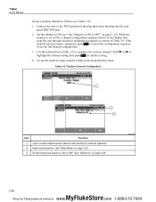
... 3-26 MyFlukeStore Shop for Fluke products online at: www. .com 1.888.610.7664 Set the channel to ON (see "Set Channels to ON or OFF. See "Read Mode" on page 3-25. Set the Debounce feature to ON or OFF" on page 3-25. Connect the wire to configure the totalizer channel. 1586A Users Manual Set up a totalizer channel as shown in Table 3-9. Use the information in Table 3-9 to...
... 3-26 MyFlukeStore Shop for Fluke products online at: www. .com 1.888.610.7664 Set the channel to ON (see "Set Channels to ON or OFF. See "Read Mode" on page 3-25. Set the Debounce feature to ON or OFF" on page 3-25. Connect the wire to configure the totalizer channel. 1586A Users Manual Set up a totalizer channel as shown in Table 3-9. Use the information in Table 3-9 to...
Product Manual
Page 83
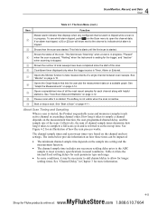
.... 4 Scan/Monitor, Record, and Data Scan Table 4-1. This field is blank until the first scan is inactive. Start or stop a scan. This field shows "Scanning" when a scan is Timer, Alarm or External. Opens the Monitor function to open the channel data. See "View Scan Data and Statistics" on page 4-12. Pause a scan after it may be impacted: • The minimum channel sample time depends on the Scan menu to...
.... 4 Scan/Monitor, Record, and Data Scan Table 4-1. This field is blank until the first scan is inactive. Start or stop a scan. This field shows "Scanning" when a scan is Timer, Alarm or External. Opens the Monitor function to open the channel data. See "View Scan Data and Statistics" on page 4-12. Pause a scan after it may be impacted: • The minimum channel sample time depends on the Scan menu to...
Product Manual
Page 91
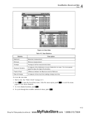
... Shop for Fluke products online at: www. .com 1.888.610.7664 Scan Statistics Statistic Description Maximum Maximum measurement. Average Average of data from its mean. To view the scan data: 1. Push to -Peak Difference between the Maximum and the Minimum. To view channel statistics, push . 4. 4 Scan/Monitor, Record, and Data Scan Figure 4-4. Rate of Change A measure of how much the readings change over time.
... Shop for Fluke products online at: www. .com 1.888.610.7664 Scan Statistics Statistic Description Maximum Maximum measurement. Average Average of data from its mean. To view the scan data: 1. Push to -Peak Difference between the Maximum and the Minimum. To view channel statistics, push . 4. 4 Scan/Monitor, Record, and Data Scan Figure 4-4. Rate of Change A measure of how much the readings change over time.

Product Manual
Page 134
... key to understand and solve the problem. Cause 2: Relay card not installed. Cause 3: Input Module has failed. 1586A Users Manual Troubleshooting In the event that the power cord is plugged in the slot. If a problem occurs, please read this section carefully and attempt to exit the screen saver. Replace the fuse once. Always replace the fuse with likely causes and solutions. Several possible problem conditions are illuminated but the display...
... key to understand and solve the problem. Cause 2: Relay card not installed. Cause 3: Input Module has failed. 1586A Users Manual Troubleshooting In the event that the power cord is plugged in the slot. If a problem occurs, please read this section carefully and attempt to exit the screen saver. Replace the fuse once. Always replace the fuse with likely causes and solutions. Several possible problem conditions are illuminated but the display...
Product Manual
Page 135
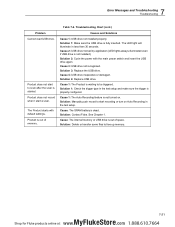
... Fluke. Product does not record when I start to be triggered. Product is not turned on Auto Recording in the test setup. Solution 3: Replace the USB drive. Cause 1: The Auto Recording feature is out of space. See Chapter 1. Solution 4: Replace USB drive. Troubleshooting Chart (cont.) Causes and Solutions Cause 1: USB drive not installed properly. Cause 2: USB driver locked by application (LED lights always illuminated even if USB drive is properly configured. Solution: Manually...
... Fluke. Product does not record when I start to be triggered. Product is not turned on Auto Recording in the test setup. Solution 3: Replace the USB drive. Cause 1: The Auto Recording feature is out of space. See Chapter 1. Solution 4: Replace USB drive. Troubleshooting Chart (cont.) Causes and Solutions Cause 1: USB drive not installed properly. Cause 2: USB driver locked by application (LED lights always illuminated even if USB drive is properly configured. Solution: Manually...


