
Fluke 125 Users Manual
Page 1
All product names are trademarks of their respective companies. ® Fluke 125 Industrial ScopeMeter Users Manual All rights reserved. GB Jan 2007, rev.1, 08/07 © 2007 Fluke Corporation.
All product names are trademarks of their respective companies. ® Fluke 125 Industrial ScopeMeter Users Manual All rights reserved. GB Jan 2007, rev.1, 08/07 © 2007 Fluke Corporation.
Fluke 125 Users Manual
Page 6
Fluke 125 Users Manual COM ...1-5 Measurement Probes & Settings 1-6 2 Scope/Meter Mode ...2-1 Introduction ...2-1 Selecting the Scope/Meter Mode 2-1 Reading the Screen ...2-2 Displaying an Unknown ... Current measurements 2-4 Temperature measurements 2-4 Power measurements 2-4 Selecting a measurement function 2-6 Freezing the Screen...2-8 Holding a Stable Reading 2-8 Making Relative Measurements 2-9 Selecting Auto/Manual Ranges 2-10 Changing the Graphic Representation on the Screen 2-10 Changing the Amplitude 2-10 Changing the Time Base 2-10 Positioning the Waveform on the Screen...
Fluke 125 Users Manual COM ...1-5 Measurement Probes & Settings 1-6 2 Scope/Meter Mode ...2-1 Introduction ...2-1 Selecting the Scope/Meter Mode 2-1 Reading the Screen ...2-2 Displaying an Unknown ... Current measurements 2-4 Temperature measurements 2-4 Power measurements 2-4 Selecting a measurement function 2-6 Freezing the Screen...2-8 Holding a Stable Reading 2-8 Making Relative Measurements 2-9 Selecting Auto/Manual Ranges 2-10 Changing the Graphic Representation on the Screen 2-10 Changing the Amplitude 2-10 Changing the Time Base 2-10 Positioning the Waveform on the Screen...
Fluke 125 Users Manual
Page 8
Fluke 125 Users Manual Reading the Screen ...4-4 Viewing the Bus Waveform Screen 4-7 Setting the Test Limits 4-8 Saving and Recalling Test Limits 4-32 5 Plotting Measurements over Time (TrendPlotTM 5-1 Introduction ...5-1 Starting/...
Fluke 125 Users Manual Reading the Screen ...4-4 Viewing the Bus Waveform Screen 4-7 Setting the Test Limits 4-8 Saving and Recalling Test Limits 4-32 5 Plotting Measurements over Time (TrendPlotTM 5-1 Introduction ...5-1 Starting/...
Fluke 125 Users Manual
Page 10
Fluke 125 Users Manual Dual Input Meter...10-4 Input A and Input B 10-4 Input A ...10-7 Advanced Meter Functions 10-8 Cursor readout ...10-8 Harmonics Measurements 10-9 Field Bus Measurements 10-9 Miscellaneous ...10-10 Environmental ...10-11 Safety...10-11 vi
Fluke 125 Users Manual Dual Input Meter...10-4 Input A and Input B 10-4 Input A ...10-7 Advanced Meter Functions 10-8 Cursor readout ...10-8 Harmonics Measurements 10-9 Field Bus Measurements 10-9 Miscellaneous ...10-10 Environmental ...10-11 Safety...10-11 vi
Fluke 125 Users Manual
Page 12
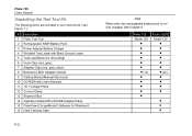
Fluke 125 Model 125 1x Fluke 125/S Model 125 2x • • • See Chapter 2. Fluke 125 Users Manual Unpacking the Test Tool Kit The following items are included in your test tool kit. (see Figure 1.): # Description 1 Fluke Test Tool 2 Rechargeable NiMH Battery Pack 3 Power Adapter/Battery Charger 4 Shielded Test Leads with Black Ground Leads 5 Test Lead Black (for Grounding) 6 Hook Clips...
Fluke 125 Model 125 1x Fluke 125/S Model 125 2x • • • See Chapter 2. Fluke 125 Users Manual Unpacking the Test Tool Kit The following items are included in your test tool kit. (see Figure 1.): # Description 1 Fluke Test Tool 2 Rechargeable NiMH Battery Pack 3 Power Adapter/Battery Charger 4 Shielded Test Leads with Black Ground Leads 5 Test Lead Black (for Grounding) 6 Hook Clips...
Fluke 125 Users Manual
Page 14
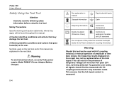
...avoid electrical shock, use only Fluke power supply, Model PM8907 (Power Adapter/Battery Charger). 0-4 See explanation in the presence of dangerous voltages of this product as unsorted municipal waste. Go to the user. This can result in manual Disposal information Equal potential inputs ... on the screen may damage the test tool. Warning Should this manual are explained in fully automatic mode. To guarantee user safety, all signals should first be found throughout the manual. Fluke 125 Users Manual Safely Using the Test Tool Attention Carefully read the following safety information...
...avoid electrical shock, use only Fluke power supply, Model PM8907 (Power Adapter/Battery Charger). 0-4 See explanation in the presence of dangerous voltages of this product as unsorted municipal waste. Go to the user. This can result in manual Disposal information Equal potential inputs ... on the screen may damage the test tool. Warning Should this manual are explained in fully automatic mode. To guarantee user safety, all signals should first be found throughout the manual. Fluke 125 Users Manual Safely Using the Test Tool Attention Carefully read the following safety information...
Fluke 125 Users Manual
Page 16
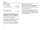
... Max. Safety is connected to protect against electrical shock. Floating Voltage From any terminal to ground 600 V CAT III Voltage ratings are used in this manual to indicate a measurement in a manner not specified may impair the protection provided by the equipment. The isolated input connectors have no exposed metal and are...! Whenever it is likely that safety has been impaired, the Test Tool must be impaired if, for AC sine wave applications and as "working voltage". Fluke 125 Users Manual Max.
... Max. Safety is connected to protect against electrical shock. Floating Voltage From any terminal to ground 600 V CAT III Voltage ratings are used in this manual to indicate a measurement in a manner not specified may impair the protection provided by the equipment. The isolated input connectors have no exposed metal and are...! Whenever it is likely that safety has been impaired, the Test Tool must be impaired if, for AC sine wave applications and as "working voltage". Fluke 125 Users Manual Max.
Fluke 125 Users Manual
Page 18
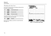
f Release. you want to restore the test tool settings as delivered from the factory, do the following: c Turn the test tool off. d Press and hold. e Press and release. Fluke 125 Users Manual Resetting the Test Tool If you will see a screen that looks like Figure 1-2. The test tool turns on, and you should hear a double beep, indicating the Reset was successful. The Screen After Reset 1-2 Figure 1-2. Now look at the display;
f Release. you want to restore the test tool settings as delivered from the factory, do the following: c Turn the test tool off. d Press and hold. e Press and release. Fluke 125 Users Manual Resetting the Test Tool If you will see a screen that looks like Figure 1-2. The test tool turns on, and you should hear a double beep, indicating the Reset was successful. The Screen After Reset 1-2 Figure 1-2. Now look at the display;
Fluke 125 Users Manual
Page 20
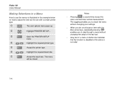
... g Accept the printer type. h Highlight the required baud rate i Accept the baud rate. Notes − Pressing a second time closes this menu and resumes normal measurement. Fluke 125 Users Manual Making Selections in a Menu How to adjust the test tool for use the menus is illustrated in a menu or button bar indicates that the function...
... g Accept the printer type. h Highlight the required baud rate i Accept the baud rate. Notes − Pressing a second time closes this menu and resumes normal measurement. Fluke 125 Users Manual Making Selections in a Menu How to adjust the test tool for use the menus is illustrated in a menu or button bar indicates that the function...
Fluke 125 Users Manual
Page 22
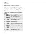
The menu will be used probe, do the following: c (A) The Input A or Input B MEASUREMENTS menu and a F1....F4 button bar pops up. (B) d Open the INPUT... Fluke 125 Users Manual Measurement Probes & Settings For the SCOPE/METER mode and the HARMONICS mode various probes can be closed. f Open the PROBE on A (B) menu g Highlight the required ...
The menu will be used probe, do the following: c (A) The Input A or Input B MEASUREMENTS menu and a F1....F4 button bar pops up. (B) d Open the INPUT... Fluke 125 Users Manual Measurement Probes & Settings For the SCOPE/METER mode and the HARMONICS mode various probes can be closed. f Open the PROBE on A (B) menu g Highlight the required ...
Fluke 125 Users Manual
Page 24
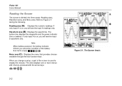
... readings. If only input A is used to display the choices. If only input A is divided into three areas: Reading area, Waveform area, and Menu area. Fluke 125 Users Manual Reading the Screen The screen is on , you will see the input A readings only.
... readings. If only input A is used to display the choices. If only input A is divided into three areas: Reading area, Waveform area, and Menu area. Fluke 125 Users Manual Reading the Screen The screen is on , you will see the input A readings only.
Fluke 125 Users Manual
Page 26
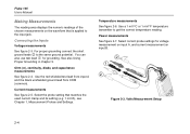
... measurement on input A, and current measurement on the waveform that matches the used current clamp and its setting (e.g. 1 mV/A), see Chapter 1, Measurement Probes and Settings. Fluke 125 Users Manual Making Measurements The reading area displays the numeric readings of the chosen measurements on input B. 2 1 2 Figure 2-3. Use the red shielded test lead from input A and...
... measurement on input A, and current measurement on the waveform that matches the used current clamp and its setting (e.g. 1 mV/A), see Chapter 1, Measurement Probes and Settings. Fluke 125 Users Manual Making Measurements The reading area displays the numeric readings of the chosen measurements on input B. 2 1 2 Figure 2-3. Use the red shielded test lead from input A and...
Fluke 125 Users Manual
Page 28
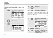
.... Observe that Hz is now the main reading. Observe that the highlight jumps to -Peak measurement for Input A, do the following : c Open the A MEASUREMENTS menu. Fluke 125 Users Manual Selecting a measurement function. d Highlight Hz.... d Highlight ON. e Turn Input B on. The former main reading has now moved to the smaller secondary reading position. (See Figure...
.... Observe that Hz is now the main reading. Observe that the highlight jumps to -Peak measurement for Input A, do the following : c Open the A MEASUREMENTS menu. Fluke 125 Users Manual Selecting a measurement function. d Highlight Hz.... d Highlight ON. e Turn Input B on. The former main reading has now moved to the smaller secondary reading position. (See Figure...
Fluke 125 Users Manual
Page 30
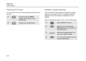
... you have a stable reading. f Turn Touch Hold off and return to normal measurement. 2-8 c Freeze the screen. HOLD appears at the bottom of the reading area. Fluke 125 Users Manual Freezing the Screen You can freeze the screen (all readings and waveforms) at any time. d Resume your measurement. Use the following procedure for the Touch...
... you have a stable reading. f Turn Touch Hold off and return to normal measurement. 2-8 c Freeze the screen. HOLD appears at the bottom of the reading area. Fluke 125 Users Manual Freezing the Screen You can freeze the screen (all readings and waveforms) at any time. d Resume your measurement. Use the following procedure for the Touch...
Fluke 125 Users Manual
Page 32
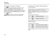
...time to automatically adjust the position, range, time base, and triggering (Connect-and-View). MANUAL appears at the bottom of the reading area disappears. Observe that AUTO at the bottom ...are from 10 ns/div to 5 s/div in normal mode. 2-10 This assures a stable display on the screen manually. Available settings are from 5 mV/div to change the graphic representation on nearly all waveforms. The bottom line shows the... area. Changing the Time Base c Increase the number of the reading area. Fluke 125 Users Manual Selecting Auto/Manual Ranges Press to select the...
...time to automatically adjust the position, range, time base, and triggering (Connect-and-View). MANUAL appears at the bottom of the reading area disappears. Observe that AUTO at the bottom ...are from 10 ns/div to 5 s/div in normal mode. 2-10 This assures a stable display on the screen manually. Available settings are from 5 mV/div to change the graphic representation on nearly all waveforms. The bottom line shows the... area. Changing the Time Base c Increase the number of the reading area. Fluke 125 Users Manual Selecting Auto/Manual Ranges Press to select the...
Fluke 125 Users Manual
Page 34
... SMOOTH. submenu. READING SMOOTH: long averaging, stable reading READING FAST: short averaging, fast response e f g h 2-12 Highlight WAVEFORM: SMOOTH to smooth the input A and input B waveform. Fluke 125 Users Manual Smoothing Waveforms and Readings To smooth the waveform, do the following: c Open the application menu.
... SMOOTH. submenu. READING SMOOTH: long averaging, stable reading READING FAST: short averaging, fast response e f g h 2-12 Highlight WAVEFORM: SMOOTH to smooth the input A and input B waveform. Fluke 125 Users Manual Smoothing Waveforms and Readings To smooth the waveform, do the following: c Open the application menu.
Fluke 125 Users Manual
Page 36
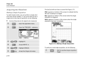
... a next single acquisition, do the following : i Wait for a trigger. d Open the TRIGGER... Wait: appears on bottom of the screen to be measured. submenu. Accept INPUT: A. Fluke 125 Users Manual Acquiring the Waveform Making a Single Acquisition To catch single events, you can perform a single shot. (One time screen update.) To set up the test tool...
... a next single acquisition, do the following : i Wait for a trigger. d Open the TRIGGER... Wait: appears on bottom of the screen to be measured. submenu. Accept INPUT: A. Fluke 125 Users Manual Acquiring the Waveform Making a Single Acquisition To catch single events, you can perform a single shot. (One time screen update.) To set up the test tool...
Fluke 125 Users Manual
Page 38
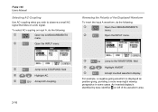
.... 2-16 e 2x Jump to the COUPLING: field f Highlight AC. An inverted display is displayed as positive-going, providing a more meaningful viewing perspective in some cases. Fluke 125 Users Manual Selecting AC-Coupling Use AC-coupling when you wish to observe a small AC signal that rides on left of the Displayed Waveform To invert the...
.... 2-16 e 2x Jump to the COUPLING: field f Highlight AC. An inverted display is displayed as positive-going, providing a more meaningful viewing perspective in some cases. Fluke 125 Users Manual Selecting AC-Coupling Use AC-coupling when you wish to observe a small AC signal that rides on left of the Displayed Waveform To invert the...
Fluke 125 Users Manual
Page 40
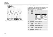
d Open the TRIGGER submenu Figure 2-15. Highlight FREE RUN. Highlight >1 Hz Select INPUT: A. Screen with automatic screen update, and to configure the auto range triggering for waveforms down to 1 Hz, do the following: c Open the applications menu. Select FREE RUN. Fluke 125 Users Manual Selecting the Trigger Parameters To trigger on the input A waveform, with all Trigger Information e f g h i 2-18 Highlight INPUT: A.
d Open the TRIGGER submenu Figure 2-15. Highlight FREE RUN. Highlight >1 Hz Select INPUT: A. Screen with automatic screen update, and to configure the auto range triggering for waveforms down to 1 Hz, do the following: c Open the applications menu. Select FREE RUN. Fluke 125 Users Manual Selecting the Trigger Parameters To trigger on the input A waveform, with all Trigger Information e f g h i 2-18 Highlight INPUT: A.

Fluke 125 Users Manual
Page 42
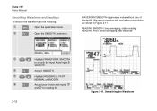
.... k Highlight POSITIVE. l Accept the video trigger selections . Measuring Video Signals To trigger on Video Signals • Apply an interlaced video signal to the red input A. Fluke 125 Users Manual Triggering on a random video line, continue from point d of the screen. Select PAL. Figure 2-17.
.... k Highlight POSITIVE. l Accept the video trigger selections . Measuring Video Signals To trigger on Video Signals • Apply an interlaced video signal to the red input A. Fluke 125 Users Manual Triggering on a random video line, continue from point d of the screen. Select PAL. Figure 2-17.


