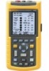
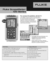
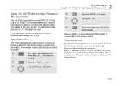
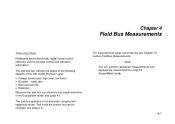
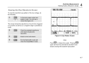
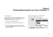
Fluke ScopeMeter Product Datasheet
Page 4
...; Optically isolated interface • Rugged compact case • New Fluke 125 gives bus health and power measurements Dual-input measurement shows both meter reading and waveform at http:// us.fluke.com/usen/products/Fluke+120. Even complex signals like frequency, duty cycle and more . The Fluke ScopeMeter 120 Series test tools and the included shielded test...
Fluke 123, 124, and 125 Scopemeter Datasheet
Page 1
...for oscilloscope, resistance and continuity measurements v NEW: Industrial networks bus health testing (Fluke 125) v = Unique selling point v NEW: Measure harmonics and power, VA, VAR, W, PF (Fluke 125) v 50 Ohm range with oscilloscope, multimeter and "paperless" recorder in one...integrated test tool, with 0.01 Ohm resolution (Fluke 125) v Cursors (Fluke 124, 125) v Up to problems in machinery, instrumentation, control and power systems. Fluke 125 Industrial ScopeMeter® • An everyday, easy-touse dual scope, meter and paperless recorder for industrial equipment service, ...
Fluke 125 Users Manual
Page 6
Fluke 125 Users Manual COM ...1-5 Measurement Probes & Settings 1-6 2 Scope/Meter Mode ...2-1 Introduction ...2-1 Selecting the Scope/Meter Mode 2-1 Reading the Screen ...2-2 Displaying an Unknown Signal with Connect-and-View™ (Auto Set 2-3 Making Measurements 2-4 Connecting the Inputs 2-4 Voltage measurements 2-4 Ohm (Ω), continuity, ...
Fluke 125 Users Manual
Page 10
Fluke 125 Users Manual Dual Input Meter...10-4 Input A and Input B 10-4 Input A ...10-7 Advanced Meter Functions 10-8 Cursor readout ...10-8 Harmonics Measurements 10-9 Field Bus Measurements 10-9 Miscellaneous ...10-10 Environmental ...10-11 Safety...10-11 vi
Fluke 125 Users Manual
Page 22
... button bar pops up. (B) d Open the INPUT... f Open the PROBE on A (B) menu g Highlight the required probe type h Accept the probe type. i 2x Close the INPUT... Fluke 125 Users Manual Measurement Probes & Settings For the SCOPE/METER mode and the HARMONICS mode various probes can be closed.
Fluke 125 Users Manual
Page 23
... test tool but gives basic examples to show how to the Scope and Meter measurements. Selecting the Scope/Meter Mode To select the Scope/Meter mode do the following: c Open the application mode menu. Chapter 2 Scope/Meter Mode Introduction The Scope/Meter mode offers you • a dual-input 40 MHz digital oscilloscope • two 5,000...
Fluke 125 Users Manual
Page 25
The trace identifier (A) is visible at the left side of the waveform. - Scope Screen After an Auto Set 2-3 2 Scope/Meter Mode Displaying an Unknown Signal with Connect-and-View™ (Auto Set) Displaying an Unknown Signal with Connect-and-View™ (Auto Set) The Connect-...
Fluke 125 Users Manual
Page 31
... the F1 ZERO ON OFF soft key enables you need to monitor the measured value in relation to turn relative measurements on and off. 2 Scope/Meter Mode Making Relative Measurements Figure 2-9. d Activate the relative measurement. (ZERO). Making a Relative Measurement The relative measurement now becomes the main reading, while the former main...
Fluke 125 Users Manual
Page 33
Waveform positioning is offered in Figure 2-10. Note: For 3 phase power measurements the waveform positions are fixed. 2 Scope/Meter Mode Changing the Graphic Representation on the screen. Observe that the trigger identifier ( ) moves horizontally on the screen. c Press until you have left any open ...
Fluke 125 Users Manual
Page 35
The screen shows the resultant envelope in time or amplitude of input waveforms over a longer period of time. 2 Scope/Meter Mode Changing the Graphic Representation on the Screen Figure 2-12. See Figure 2-12. Repeat the first two actions of the waveform. f (3x) Start monitoring the ...
Fluke 125 Users Manual
Page 37
... chart recorder. g Highlight ROLL h (2x) Start Recording. Recording Slow Signals over Longer Period of waveform activity and is pressed. (See figure 2-14.) 2-15 submenu. 2 Scope/Meter Mode Acquiring the Waveform e Highlight A. Recording Waveforms over a Long Period of Time The roll mode function supplies a visual log of Time g Freeze Recording. d Open the...
Fluke 125 Users Manual
Page 39
.... Trigger icons on the screen indicate the trigger level and slope. (See Figure 2-15.) Note: For 3 phase power measurements the trigger settings are fixed. 2 Scope/Meter Mode Triggering on a Waveform Setting Trigger Level and Slope For quick operation, use the AUTO SET key to automatically trigger on the second time division...
Fluke 125 Users Manual
Page 41
... screen is TTL compatible. Note Setting the automatic triggering to normal measurement. Trigger level is fixed and is updated only when valid triggers occur. 2 Scope/Meter Mode Triggering on a Waveform Isolated Triggering Use the optically isolated trigger probe (ITP120, optional) to isolate the test tool from a trigger waveform. j Accept all trigger...
Fluke 125 Users Manual
Page 43
Triggering on a Waveform To choose line 135, do the following: c Enable video line selection. l Accept the video trigger selections . 2-21 d Select number 135. j Select SELECT k Highlight POSITIVE. To measure on a selected video line, continue from point h of the previous example as follows: i Highlight SELECT 2 Scope/Meter Mode Triggering on a Specific Video Line To view a specific video line in more detail you can select the line number.
Fluke 125 Users Manual
Page 44
... the desired position on the screen. Using Horizontal Cursors on waveforms. For 3 phase power measurements cursors are displayed. Fluke 125 Users Manual Making Cursor Measurements Cursors allow you can still use the cursors for a voltage measurement, do the following: c From Scope/Meter mode, display the Cursor Key functions: d Press to highlight . Figure 2-18.
Fluke 125 Users Manual
Page 45
... displayed behind 1/t if exactly 1 signal period is between the two markers (See Figure 2-19). g Move the left cursor. Using Vertical Cursors on the waveform. 2 Scope/Meter Mode Making Cursor Measurements Figure 2-19.
Fluke 125 Users Manual
Page 47
The test tool is for High Frequency Measurements. Probe Attenuation. Probe Adjustment. How to its inputs: high frequency adjustment is not necessary. 2 Scope/Meter Mode Using the 10:1 Probe for a Probe connected to input A: c The Input A MEASUREMENTS menu and a F1....F4 button bar pops up. The loading of the ...
Fluke 125 Users Manual
Page 55
..., see page 4-8. baud rate • Rise and fall time • Distortion Moreover the test tool can perform resistance measurements and capacitance measurements using the Scope/Meter mode. 4-1 Test limits are bi-directional, digital, serial control networks used in process control and industrial automation. For supported bus types and protocols see page...
Fluke 125 Users Manual
Page 61
f Exit the Bushealth mode and enter the Scope/Meter mode. 4 Field Bus Measurements Viewing the Bus Waveform Screen Figure 4-4. d Clear the persisted waveforms and restart showing the waveform. e Return to freeze the screen. Eye ...
Fluke 125 Users Manual
Page 65
... application mode menu. Chapter 5 Plotting Measurements over Time (TrendPlotTM) Introduction The TrendPlot™ function plots a graph derived from the MAIN (large) readings in the SCOPE/METER mode or in the HARMONICS mode as a function of the most recent change.