Service Manual
Page 1
Printed in the Netherlands All product names are trademarks of their respective companies. All rights reserved. 123/124 Industrial ScopeMeter Service Manual 4822 872 05389 February 2003 © 2003 Fluke Corporation.
Printed in the Netherlands All product names are trademarks of their respective companies. All rights reserved. 123/124 Industrial ScopeMeter Service Manual 4822 872 05389 February 2003 © 2003 Fluke Corporation.

Service Manual
Page 4
... Ohm 5-12 5.6.7 Gain Ohm 5-13 5.6.8 Capacitance Gain Low and High 5-14 5.6.9 Capacitance Clamp & Zero 5-14 5.6.10 Capacitance Gain 5-15 5.7 Save Calibration Data and Exit 5-15 123/124 Service Manual 3.2.5 Start-up Sequence, Operating Modes 3-7 3.3 Detailed Circuit Descriptions 3-9 3.3.1 Power Circuit 3-9 3.3.2 Channel A -
... Ohm 5-12 5.6.7 Gain Ohm 5-13 5.6.8 Capacitance Gain Low and High 5-14 5.6.9 Capacitance Clamp & Zero 5-14 5.6.10 Capacitance Gain 5-15 5.7 Save Calibration Data and Exit 5-15 123/124 Service Manual 3.2.5 Start-up Sequence, Operating Modes 3-7 3.3 Detailed Circuit Descriptions 3-9 3.3.1 Power Circuit 3-9 3.3.2 Channel A -

Service Manual
Page 7
List of Tables Table Title Page 2-1.No Visible Trace Disturbance 2-14 2-2.Trace Disturbance < 10 2-14 2-3.Multimeter Disturbance < 1 2-14 3-1.Fluke 123 Main Blocks 3-3 3-2.Fluke 123 Operating Modes 3-9 3-3.Voltage Ranges And Trace Sensitivity 3-18 3-4.Ohms Ranges, Trace Sensitivity, and Current 3-18 3-5.Capacitance Ranges, Current, and Pulse Width 3-20 3-6.D-ASIC PWM Signals 3-...
List of Tables Table Title Page 2-1.No Visible Trace Disturbance 2-14 2-2.Trace Disturbance < 10 2-14 2-3.Multimeter Disturbance < 1 2-14 3-1.Fluke 123 Main Blocks 3-3 3-2.Fluke 123 Operating Modes 3-9 3-3.Voltage Ranges And Trace Sensitivity 3-18 3-4.Ohms Ranges, Trace Sensitivity, and Current 3-18 3-5.Capacitance Ranges, Current, and Pulse Width 3-20 3-6.D-ASIC PWM Signals 3-...

Service Manual
Page 9
Input Voltage v.s. List of Figures Figure Title Page 2-2.Max. Frequency for VP40 10:1 Voltage Probe 2-13 3-1.Fluke 123 Block Diagram 3-2 3-2.Fluke 123 Start-up Sequence, Operating Modes 3-8 3-3.Power Supply Block Diagram 3-9 3-4.CHAGATE Control Voltage 3-12 3-5.Fly-Back Converter Current and Control Voltage 3-12 3-6.Fly-Back Converter Block ...
Input Voltage v.s. List of Figures Figure Title Page 2-2.Max. Frequency for VP40 10:1 Voltage Probe 2-13 3-1.Fluke 123 Block Diagram 3-2 3-2.Fluke 123 Start-up Sequence, Operating Modes 3-8 3-3.Power Supply Block Diagram 3-9 3-4.CHAGATE Control Voltage 3-12 3-5.Fly-Back Converter Current and Control Voltage 3-12 3-6.Fly-Back Converter Block ...

Service Manual
Page 10
123/124 Service Manual 5-6. Volt Gain Calibration Input Connections
123/124 Service Manual 5-6. Volt Gain Calibration Input Connections

Service Manual
Page 14
... the List of the instrument may only be gained by components obtained through your local FLUKE organization. Capacitors inside the instrument can hold their charge even if the instrument has been separated from all voltage sources. 123/124 Service Manual 1.5 Impaired Safety Whenever it is likely that safety has been impaired, the...
... the List of the instrument may only be gained by components obtained through your local FLUKE organization. Capacitors inside the instrument can hold their charge even if the instrument has been separated from all voltage sources. 123/124 Service Manual 1.5 Impaired Safety Whenever it is likely that safety has been impaired, the...

Service Manual
Page 17
... by the manufacturer may impair protection provided by the equipment. 2.2 Dual Input Oscilloscope 2.2.1 Vertical Frequency Response DC Coupled: excluding probes and test leads: Fluke 123 (via BB120) Fluke 124 (via BB120) DC to 20 MHz (-3 dB) DC to 40 MHz (-3 dB) with STL120 1:1 shielded test leads: DC to 12.5... MHz (-3 dB) DC to 20 MHz (-6 dB) with VP40 10:1 probe: Fluke 123 (optional accessory) Fluke 124 (standard accessory) DC to 20 MHz (-3 dB) DC to 40 MHz (-3 dB) AC Coupled (LF roll off): excluding probes and test leads...
... by the manufacturer may impair protection provided by the equipment. 2.2 Dual Input Oscilloscope 2.2.1 Vertical Frequency Response DC Coupled: excluding probes and test leads: Fluke 123 (via BB120) Fluke 124 (via BB120) DC to 20 MHz (-3 dB) DC to 40 MHz (-3 dB) with STL120 1:1 shielded test leads: DC to 12.5... MHz (-3 dB) DC to 20 MHz (-6 dB) with VP40 10:1 probe: Fluke 123 (optional accessory) Fluke 124 (standard accessory) DC to 20 MHz (-3 dB) DC to 40 MHz (-3 dB) AC Coupled (LF roll off): excluding probes and test leads...

Service Manual
Page 18
123/124 Service Manual Display Modes A, -A, B, -B Max. Vertical Move Max. Input Voltage A and B Direct, with test leads, or with VP40 Probe 600 Vrms with BB120 300 ... After changing time base or sensitivity Normal & Single mode ±0.04 divisions (= ±1 pixel) 2.2.2 Horizontal Scope Modes Normal, Single, Roll Ranges Normal: equivalent sampling (Fluke 123) equivalent sampling (Fluke 124) real time sampling 20 ns to 500 ns/div 10 ns to 500 ns/div 1 µs to 5 s/div Single (real time) 1 µs to...
123/124 Service Manual Display Modes A, -A, B, -B Max. Vertical Move Max. Input Voltage A and B Direct, with test leads, or with VP40 Probe 600 Vrms with BB120 300 ... After changing time base or sensitivity Normal & Single mode ±0.04 divisions (= ±1 pixel) 2.2.2 Horizontal Scope Modes Normal, Single, Roll Ranges Normal: equivalent sampling (Fluke 123) equivalent sampling (Fluke 124) real time sampling 20 ns to 500 ns/div 10 ns to 500 ns/div 1 µs to 5 s/div Single (real time) 1 µs to...

Service Manual
Page 19
... Polarity Sensitivity 0.5 divisions or 5 mV 1.5 divisions 4 divisions 0.5 divisions or 5 mV 1.5 divisions 4 divisions ±0.5 div. 2 Characteristics 2.3 Dual Input Meter Sensitivity A and B (Fluke 123) @ DC to 5 MHz @ 25 MHz @ 40 MHz Sensitivity A and B (Fluke 124) @ DC to 28 °C. Suppresses noise from 18 °C to 5 MHz @ 40 MHz @ 60 MHz Voltage level error Slope Video...
... Polarity Sensitivity 0.5 divisions or 5 mV 1.5 divisions 4 divisions 0.5 divisions or 5 mV 1.5 divisions 4 divisions ±0.5 div. 2 Characteristics 2.3 Dual Input Meter Sensitivity A and B (Fluke 123) @ DC to 5 MHz @ 25 MHz @ 40 MHz Sensitivity A and B (Fluke 124) @ DC to 28 °C. Suppresses noise from 18 °C to 5 MHz @ 40 MHz @ 60 MHz Voltage level error Slope Video...

Service Manual
Page 20
... Ranges 500 mV, 5V, 50V, 500V, 1250V Accuracy: Max peak or Min peak Peak-to-Peak 5% of full scale 10% of any signal crest factor. 123/124 Service Manual Full Scale Reading 5000 counts Move influence ±6 counts max. True RMS Voltages (VAC and VAC+DC) Ranges 500 mV, 5V, 50V... scale Full Scale Reading 500 counts Frequency (Hz) Ranges 1Hz, 10Hz, 100Hz, 1 kHz, 10 kHz, 100 kHz, 1 MHz, 10 MHz, and 50 MHz (Fluke 123) or 70 MHz (Fluke 124). Frequency Range for 5 to 100% of range DC coupled: DC to 60 Hz (VAC+DC) 1 Hz to 60 Hz (VAC) ±(1% +10 counts...
... Ranges 500 mV, 5V, 50V, 500V, 1250V Accuracy: Max peak or Min peak Peak-to-Peak 5% of full scale 10% of any signal crest factor. 123/124 Service Manual Full Scale Reading 5000 counts Move influence ±6 counts max. True RMS Voltages (VAC and VAC+DC) Ranges 500 mV, 5V, 50V... scale Full Scale Reading 500 counts Frequency (Hz) Ranges 1Hz, 10Hz, 100Hz, 1 kHz, 10 kHz, 100 kHz, 1 MHz, 10 MHz, and 50 MHz (Fluke 123) or 70 MHz (Fluke 124). Frequency Range for 5 to 100% of range DC coupled: DC to 60 Hz (VAC+DC) 1 Hz to 60 Hz (VAC) ±(1% +10 counts...

Service Manual
Page 21
2 Characteristics 2.3 Dual Input Meter Accuracy: @1Hz to 1 MHz @1 MHz to 10 MHz @10 MHz to 50 MHz (Fluke 123) @10 MHz to 70 MHz (Fluke 124) (50 MHz in Autorange) Full Scale Reading ±(0.5% +2 counts) ±(1.0% +2 counts) ±(2.5% +2 counts) ±(2.5% +2 counts) 10 000 counts Duty Cycle (DUTY) Range Frequency Range ...
2 Characteristics 2.3 Dual Input Meter Accuracy: @1Hz to 1 MHz @1 MHz to 10 MHz @10 MHz to 50 MHz (Fluke 123) @10 MHz to 70 MHz (Fluke 124) (50 MHz in Autorange) Full Scale Reading ±(0.5% +2 counts) ±(1.0% +2 counts) ±(2.5% +2 counts) ±(2.5% +2 counts) 10 000 counts Duty Cycle (DUTY) Range Frequency Range ...

Service Manual
Page 22
123/124 Service Manual Full Scale Reading Phase Modes Range Accuracy Resolution 2.3.2 Input A Ohm (Ω) Ranges Accuracy Full Scale Reading 500Ω to 5 MΩ 30 MΩ ...
123/124 Service Manual Full Scale Reading Phase Modes Range Accuracy Resolution 2.3.2 Input A Ohm (Ω) Ranges Accuracy Full Scale Reading 500Ω to 5 MΩ 30 MΩ ...
Service Manual
Page 24
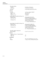
... Manual Waveform display: Vertical Horizontal Backlight Power External: Input Voltage Power Input Connector Internal Battery Pack BP120 (Fluke 123): Battery Power Operating Time Charging Time 8 divisions of 20 pixels 9.6 divisions of 25 pixels Cold Cathode Fluorescent (CCFL) via Power Adapter ... tool off 60 hours with test tool on 12 ... 19 hours with refresh cycle Allowable ambient temperature during charging Memory Number of Screen + Setup Memories Fluke 123 Fluke 124 Mechanical Size Weight 0 to 45 °C (32 to 113 °F) 10 20 232 x 115 x 50 mm (9.1 x 4.5 x 2 in) 1.2 kg (2.5 lbs), including...
... Manual Waveform display: Vertical Horizontal Backlight Power External: Input Voltage Power Input Connector Internal Battery Pack BP120 (Fluke 123): Battery Power Operating Time Charging Time 8 divisions of 20 pixels 9.6 divisions of 25 pixels Cold Cathode Fluorescent (CCFL) via Power Adapter ... tool off 60 hours with test tool on 12 ... 19 hours with refresh cycle Allowable ambient temperature during charging Memory Number of Screen + Setup Memories Fluke 123 Fluke 124 Mechanical Size Weight 0 to 45 °C (32 to 113 °F) 10 20 232 x 115 x 50 mm (9.1 x 4.5 x 2 in) 1.2 kg (2.5 lbs), including...

Service Manual
Page 26
... • EN61010-1 (1993) (IEC1010-1) • CAN/CSA-C22.2 No.1010.1-92 (including approval) • UL3111-1 (including approval) Max. Maximum Input Voltage vs Frequency ST8112.CGM 123/124 Service Manual Enclosure Protection IP51, ref: IEC529 2.7 Service and Maintenance Calibration Interval 1 Year 2.8 Safety Designed for measurements on input, with leads, with VP40 With...
... • EN61010-1 (1993) (IEC1010-1) • CAN/CSA-C22.2 No.1010.1-92 (including approval) • UL3111-1 (including approval) Max. Maximum Input Voltage vs Frequency ST8112.CGM 123/124 Service Manual Enclosure Protection IP51, ref: IEC529 2.7 Service and Maintenance Calibration Interval 1 Year 2.8 Safety Designed for measurements on input, with leads, with VP40 With...

Service Manual
Page 28
... 500 µF Test tool ranges not specified in Table 2-1 and Table 2-2 may have a disturbance of more than 10% of full scale. 2-14 123/124 Service Manual 2.9 EMC Immunity The Fluke 123/124, including standard accessories, conforms with the EEC directive 89/336 for EMC immunity, as defined by IEC1000-4-3, with the addition of...
... 500 µF Test tool ranges not specified in Table 2-1 and Table 2-2 may have a disturbance of more than 10% of full scale. 2-14 123/124 Service Manual 2.9 EMC Immunity The Fluke 123/124, including standard accessories, conforms with the EEC directive 89/336 for EMC immunity, as defined by IEC1000-4-3, with the addition of...

Service Manual
Page 31
... input coupling and Ω/F relay control Voltage reference source Analog to as C-ASIC (Channel ASIC), T-ASIC (Trigger ASIC), P-ASIC (Power ASIC), and D-ASIC (Digital ASIC). 3-3 Fluke 123/124 Main Blocks Main Functions ASIC CHANNEL A CHANNEL B TRIGGER DIGITAL POWER Input A signal (V-Ω-F) conditioning Input B signal (V) conditioning Trigger selection and conditioning Current source for...
... input coupling and Ω/F relay control Voltage reference source Analog to as C-ASIC (Channel ASIC), T-ASIC (Trigger ASIC), P-ASIC (Power ASIC), and D-ASIC (Digital ASIC). 3-3 Fluke 123/124 Main Blocks Main Functions ASIC CHANNEL A CHANNEL B TRIGGER DIGITAL POWER Input A signal (V-Ω-F) conditioning Input B signal (V) conditioning Trigger selection and conditioning Current source for...

Service Manual
Page 32
... Analog to the T-ASIC via the APWM bus. From the ADC samples to the C-ASIC, via the Sync(hronization) Pulse Separator circuit (TVOUT-TVSYNC lines). 123/124 Service Manual 3.2.1 Channel A, Channel B Measurement Circuits The Channel A and Channel B circuit are provided by the T-ASIC. 3.2.2 Trigger Circuit The T ASIC selects one of the...
... Analog to the T-ASIC via the APWM bus. From the ADC samples to the C-ASIC, via the Sync(hronization) Pulse Separator circuit (TVOUT-TVSYNC lines). 123/124 Service Manual 3.2.1 Channel A, Channel B Measurement Circuits The Channel A and Channel B circuit are provided by the T-ASIC. 3.2.2 Trigger Circuit The T ASIC selects one of the...

Service Manual
Page 34
... supply voltage powers the D-ASIC, RAM and ROM. temperature (TEMP), voltage (BATVOLT), current (IBAT). supply voltage for various test tool circuits. A linear regulator in a matrix. 123/124 Service Manual drivers, and a fluorescent back light lamp. The back light supply voltage is connected, the battery pack supplies the VBAT voltage. It is...
... supply voltage powers the D-ASIC, RAM and ROM. temperature (TEMP), voltage (BATVOLT), current (IBAT). supply voltage for various test tool circuits. A linear regulator in a matrix. 123/124 Service Manual drivers, and a fluorescent back light lamp. The back light supply voltage is connected, the battery pack supplies the VBAT voltage. It is...

Service Manual
Page 36
A refresh cycle takes 16 hours maximum, depending on , and the power adapter is connected. 123/124 Service Manual Battery Refresh In the following situations the batteries will be prompted for this action when he turns the test tool on, directly ...following the start up Sequence, Operating Modes Table 3-2 shows an overview of the test tool operating modes. 3-8 Fluke 123/124 Start-up screen. VGARVAL=L Idle mode VGARVAL=H Off mode TURN ON or MAINVAL=H Mask StartUp Flash ROM OK Flash ROM NOT OK OR Mask...
A refresh cycle takes 16 hours maximum, depending on , and the power adapter is connected. 123/124 Service Manual Battery Refresh In the following situations the batteries will be prompted for this action when he turns the test tool on, directly ...following the start up Sequence, Operating Modes Table 3-2 shows an overview of the test tool operating modes. 3-8 Fluke 123/124 Start-up screen. VGARVAL=L Idle mode VGARVAL=H Off mode TURN ON or MAINVAL=H Mask StartUp Flash ROM OK Flash ROM NOT OK OR Mask...

Service Manual
Page 37
... VADALOW 8 VADAPTER 20 CONTROL 80 CHARCURR 100kHz CO4S3C C553 linear regulator linear regulator 12 V565 MAINVAL V566 18 P7VCHA 22 +12V C507 POWER ASIC Figure 3-3. Fluke 123/124 Operating Modes Conditions Remark No power adapter and no battery No power adapter connected, battery installed, test tool off No valid instrument software, or...
... VADALOW 8 VADAPTER 20 CONTROL 80 CHARCURR 100kHz CO4S3C C553 linear regulator linear regulator 12 V565 MAINVAL V566 18 P7VCHA 22 +12V C507 POWER ASIC Figure 3-3. Fluke 123/124 Operating Modes Conditions Remark No power adapter and no battery No power adapter connected, battery installed, test tool off No valid instrument software, or...