
Service Manual
Page 13
... on the instrument. 1.3 Caution and Warning Statements Caution Used to indicate correct operating or maintenance procedures to prevent damage to be found throughout the manual. Specific warning and caution statements, where they apply, will be done only by qualified service personnel. Warning Calls attention to a potential danger that both operating and...
... on the instrument. 1.3 Caution and Warning Statements Caution Used to indicate correct operating or maintenance procedures to prevent damage to be found throughout the manual. Specific warning and caution statements, where they apply, will be done only by qualified service personnel. Warning Calls attention to a potential danger that both operating and...

Service Manual
Page 18
...or sensitivity Normal & Single mode ±0.04 divisions (= ±1 pixel) 2.2.2 Horizontal Scope Modes Normal, Single, Roll Ranges Normal: equivalent sampling (Fluke 123) equivalent sampling (Fluke 124) real time sampling 20 ns to 500 ns/div 10 ns to 500 ns/div 1 µs to 5 s/div Single (real time... ITP120 (optional accessory) Input Voltage A and B Direct, with test leads, or with VP40 Probe 600 Vrms with BB120 300 Vrms (For detailed specifications see "2.8 Safety") Max. Floating Voltage from any terminal to ground 600 Vrms, up to 1.25 GS/s Real time sampling: 1 µs to...
...or sensitivity Normal & Single mode ±0.04 divisions (= ±1 pixel) 2.2.2 Horizontal Scope Modes Normal, Single, Roll Ranges Normal: equivalent sampling (Fluke 123) equivalent sampling (Fluke 124) real time sampling 20 ns to 500 ns/div 10 ns to 500 ns/div 1 µs to 5 s/div Single (real time... ITP120 (optional accessory) Input Voltage A and B Direct, with test leads, or with VP40 Probe 600 Vrms with BB120 300 Vrms (For detailed specifications see "2.8 Safety") Max. Floating Voltage from any terminal to ground 600 Vrms, up to 1.25 GS/s Real time sampling: 1 µs to...

Service Manual
Page 19
... base, trigger levels, trigger gap, and hold-off. max. For voltage measurements with 10:1 probe, add probe uncertainty +1%. Add 0.1x (specific accuracy) for each °C below 18 °C or above 28 °C. Suppresses noise from 18 °C to 28 °C. Manual ...(% of reading + number of counts) from a waveform. 2 Characteristics 2.3 Dual Input Meter Sensitivity A and B (Fluke 123) @ DC to 5 MHz @ 25 MHz @ 40 MHz Sensitivity A and B (Fluke 124) @ DC to 40 ns glitches and displays analog-like persistence waveform. Positive, Negative Interlaced video signals only Lines...
... base, trigger levels, trigger gap, and hold-off. max. For voltage measurements with 10:1 probe, add probe uncertainty +1%. Add 0.1x (specific accuracy) for each °C below 18 °C or above 28 °C. Suppresses noise from 18 °C to 28 °C. Manual ...(% of reading + number of counts) from a waveform. 2 Characteristics 2.3 Dual Input Meter Sensitivity A and B (Fluke 123) @ DC to 5 MHz @ 25 MHz @ 40 MHz Sensitivity A and B (Fluke 124) @ DC to 40 ns glitches and displays analog-like persistence waveform. Positive, Negative Interlaced video signals only Lines...

Service Manual
Page 31
...Ω/F relay control Voltage reference source Analog to get familiar with the test tool basic build-up around an Application Specific Integrated Circuit (ASIC). The ASIC's are referred to the shielded input banana jackets. For all measurements, input signals are...9-6 Figure 9-7 Figure 9-6 All circuits, except the LCD unit and the KEYBOARD, are derived from the same input signal samples. See Table 3-1. Fluke 123/124 Main Blocks Main Functions ASIC CHANNEL A CHANNEL B TRIGGER DIGITAL POWER Input A signal (V-Ω-F) conditioning Input B signal (V) conditioning Trigger selection...
...Ω/F relay control Voltage reference source Analog to get familiar with the test tool basic build-up around an Application Specific Integrated Circuit (ASIC). The ASIC's are referred to the shielded input banana jackets. For all measurements, input signals are...9-6 Figure 9-7 Figure 9-6 All circuits, except the LCD unit and the KEYBOARD, are derived from the same input signal samples. See Table 3-1. Fluke 123/124 Main Blocks Main Functions ASIC CHANNEL A CHANNEL B TRIGGER DIGITAL POWER Input A signal (V-Ω-F) conditioning Input B signal (V) conditioning Trigger selection...
Service Manual
Page 61
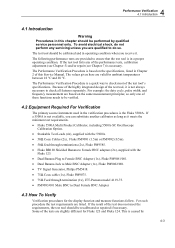
... width, and frequency measurement are listed. For each procedure the test requirements are based on the specifications, listed in Chapter 2 of the test tool's specifications. To avoid electrical shock, do so. The Performance Verification Procedure is not available, you can... substitute another calibrator as long as it meets the minimum test requirements. • Fluke 5500A Multi Product Calibrator, including 5500A-SC...
... width, and frequency measurement are listed. For each procedure the test requirements are based on the specifications, listed in Chapter 2 of the test tool's specifications. To avoid electrical shock, do so. The Performance Verification Procedure is not available, you can... substitute another calibrator as long as it meets the minimum test requirements. • Fluke 5500A Multi Product Calibrator, including 5500A-SC...

Service Manual
Page 91
Explanation of this step, the calibration process is in progress; This means that the unit meets the specifications related to this step! It does not necessarily mean that the last time this step, the calibration process is not started . The... the Maintenance mode Readings and traces After completing a calibration step, readings and traces are saved. This means that the unit will not meet the specifications if the calibration data are shown using the new calibration data. 5-5 b. The calibration data of screen messages and key functions. Continue with either ...
Explanation of this step, the calibration process is in progress; This means that the unit meets the specifications related to this step! It does not necessarily mean that the last time this step, the calibration process is not started . The... the Maintenance mode Readings and traces After completing a calibration step, readings and traces are saved. This means that the unit will not meet the specifications if the calibration data are shown using the new calibration data. 5-5 b. The calibration data of screen messages and key functions. Continue with either ...
