Operation Manual
Page 3
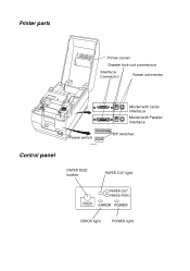
Printer parts Printer coverr Drawer kick-out connectors Interface Connector Power connector Power switch Model with Serial Interface Model with Parallel Interface DIP switches Control panel PAPER FEED button PAPER OUT light ERROR light POWER light
Printer parts Printer coverr Drawer kick-out connectors Interface Connector Power connector Power switch Model with Serial Interface Model with Parallel Interface DIP switches Control panel PAPER FEED button PAPER OUT light ERROR light POWER light
Operation Manual
Page 5
... this equipment in a residential area is operated in accordance with the limits for a Class A digital device, pursuant to Part 15 of a non-shielded printer interface cable to this printer will be required to correct the interference at his own expense. FCC CLASS A FCC Compliance Statement For American Users This equipment has been...
... this equipment in a residential area is operated in accordance with the limits for a Class A digital device, pursuant to Part 15 of a non-shielded printer interface cable to this printer will be required to correct the interference at his own expense. FCC CLASS A FCC Compliance Statement For American Users This equipment has been...
Operation Manual
Page 6
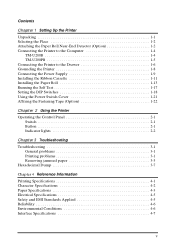
... 1-1 Selecting the Place 1-2 Attaching the Paper Roll Near-End Detector (Option 1-2 Connecting the Printer to the Computer 1-4 TM-U200B 1-4 TM-U200PB 1-5 Connecting the Printer to the Drawer 1-6 Grounding the Printer 1-8 Connecting the Power Supply 1-9 Installing the Ribbon Cassette 1-11 Installing the Paper Roll 1-13 Running the Self Test 1-17 Setting the DIP Switches 1-18 Using ...
... 1-1 Selecting the Place 1-2 Attaching the Paper Roll Near-End Detector (Option 1-2 Connecting the Printer to the Computer 1-4 TM-U200B 1-4 TM-U200PB 1-5 Connecting the Printer to the Drawer 1-6 Grounding the Printer 1-8 Connecting the Power Supply 1-9 Installing the Ribbon Cassette 1-11 Installing the Paper Roll 1-13 Running the Self Test 1-17 Setting the DIP Switches 1-18 Using ...
Operation Manual
Page 7
... t Flexible paper feed setting permits printing of weighing or measuring. Introduction Features The TM-U200 Series printers are the following 2 models. • Two-color type with a serial interface • Two-color type with a parallel interface The main features of the TM-U200 Series printers are one for printing the results of any user-defined format t Command...
... t Flexible paper feed setting permits printing of weighing or measuring. Introduction Features The TM-U200 Series printers are the following 2 models. • Two-color type with a serial interface • Two-color type with a parallel interface The main features of the TM-U200 Series printers are one for printing the results of any user-defined format t Command...
Operation Manual
Page 8
t Chapter 3 contains troubleshooting information. WARNING: Warnings must be followed carefully to your printer. Reference t Chapter 4 contains specifications. t Chapter 2 contains information on unpacking the printer, setting it up, running the self test, and setting the DIP switches. CAUTION: Cautions must be observed to ... to avoid serious bodily injury. About This Manual Setting Up and Using t Chapter 1 contains information on using the printer. Notes, Cautions, and Warnings Note: Notes have important information and useful tips on the operation of your equipment. iv
t Chapter 3 contains troubleshooting information. WARNING: Warnings must be followed carefully to your printer. Reference t Chapter 4 contains specifications. t Chapter 2 contains information on unpacking the printer, setting it up, running the self test, and setting the DIP switches. CAUTION: Cautions must be observed to ... to avoid serious bodily injury. About This Manual Setting Up and Using t Chapter 1 contains information on using the printer. Notes, Cautions, and Warnings Note: Notes have important information and useful tips on the operation of your equipment. iv
Operation Manual
Page 9
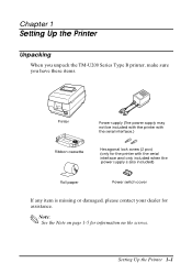
Chapter 1 Setting Up the Printer Unpacking When you unpack the TM-U200 Series Type B printer, make sure you have these items. Printer Ribbon cassette Power supply (The power supply may not be included with the printer with the serial interface.) Hexagonal lock screw (2 pcs) (only for the printer with the serial interface and only included when the power supply is also included) Roll paper Power switch cover If any item is missing or damaged, please contact your dealer for information on the screws. Note: See the Note on page 1-5 for assistance. Setting Up the Printer 1-1
Chapter 1 Setting Up the Printer Unpacking When you unpack the TM-U200 Series Type B printer, make sure you have these items. Printer Ribbon cassette Power supply (The power supply may not be included with the printer with the serial interface.) Hexagonal lock screw (2 pcs) (only for the printer with the serial interface and only included when the power supply is also included) Roll paper Power switch cover If any item is missing or damaged, please contact your dealer for information on the screws. Note: See the Note on page 1-5 for assistance. Setting Up the Printer 1-1
Operation Manual
Page 10
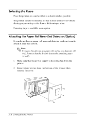
...you do not have a paper roll near-end detector or do not want to 12.5 mm so that is as horizontal as an option. The printer should be installed so that the power supply is available as possible. then remove the cover. 1-2 Setting Up the... Printer Fastening tape is disconnected from the bottom of the printer; Make sure that it , skip this detector, use this section. Selecting the Place Place the printer on a surface that the detector detects the remaining paper correctly. 1. Remove four ...
...you do not have a paper roll near-end detector or do not want to 12.5 mm so that is as horizontal as an option. The printer should be installed so that the power supply is available as possible. then remove the cover. 1-2 Setting Up the... Printer Fastening tape is disconnected from the bottom of the printer; Make sure that it , skip this detector, use this section. Selecting the Place Place the printer on a surface that the detector detects the remaining paper correctly. 1. Remove four ...
Operation Manual
Page 11
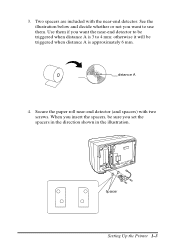
Two spacers are included with the near -end detector (and spacers) with two screws. See the illustration below and decide whether or not you want the near-end detector to be triggered when distance A is 3 to use them if you set the spacers in the direction shown in the illustration. Secure the paper roll near -end detector. Use them . 3. distance A 4. otherwise it will be triggered when distance A is approximately 6 mm. When you insert the spacers, be sure you want to 4 mm; Spacer Setting Up the Printer 1-3
Two spacers are included with the near -end detector (and spacers) with two screws. See the illustration below and decide whether or not you want the near-end detector to be triggered when distance A is 3 to use them if you set the spacers in the direction shown in the illustration. Secure the paper roll near -end detector. Use them . 3. distance A 4. otherwise it will be triggered when distance A is approximately 6 mm. When you insert the spacers, be sure you want to 4 mm; Spacer Setting Up the Printer 1-3
Operation Manual
Page 12
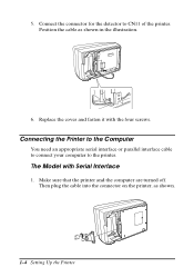
Position the cable as shown. 1-4 Setting Up the Printer The Model with the four screws. Make sure that the printer and the computer are turned off. Connect the connector for the detector to the printer. Connecting the Printer to the Computer You need an appropriate serial interface or parallel interface cable to connect your computer to CN11 of the printer. Replace the cover and fasten it with Serial Interface 1. 5. Then plug the cable into the connector on the printer, as shown in the illustration. 6.
Position the cable as shown. 1-4 Setting Up the Printer The Model with the four screws. Make sure that the printer and the computer are turned off. Connect the connector for the detector to the printer. Connecting the Printer to the Computer You need an appropriate serial interface or parallel interface cable to connect your computer to CN11 of the printer. Replace the cover and fasten it with Serial Interface 1. 5. Then plug the cable into the connector on the printer, as shown in the illustration. 6.
Operation Manual
Page 13
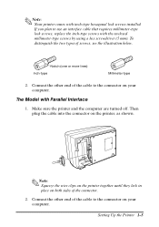
...the enclosed millimeter-type screws by using a hex screwdriver (5 mm). Note: Squeeze the wire clips on the printer together until they lock in place on your computer. Setting Up the Printer 1-5 Notch (one or more lines) Inch-type Millimeter-type 2. Connect the other end of the cable ..., see the illustration below. If you plan to the connector on the printer, as shown. Make sure the printer and the computer are turned off. To distinguish the two types of the connector. 2. Note: Your printer comes with Parallel Interface 1. The Model with inch-type hexagonal lock screws ...
...the enclosed millimeter-type screws by using a hex screwdriver (5 mm). Note: Squeeze the wire clips on the printer together until they lock in place on your computer. Setting Up the Printer 1-5 Notch (one or more lines) Inch-type Millimeter-type 2. Connect the other end of the cable ..., see the illustration below. If you plan to the connector on the printer, as shown. Make sure the printer and the computer are turned off. To distinguish the two types of the connector. 2. Note: Your printer comes with Parallel Interface 1. The Model with inch-type hexagonal lock screws ...
Operation Manual
Page 14
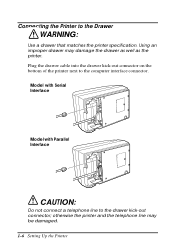
Plug the drawer cable into the drawer kick-out connector on the bottom of the printer next to the drawer kick-out connector; Model with Serial Interface Model with Parallel Interface CAUTION: Do not connect a telephone line to the computer interface connector. otherwise the printer and the telephone line may damage the drawer as well as the printer. Using an improper drawer may be damaged. 1-6 Setting Up the Printer Connecting the Printer to the Drawer WARNING: Use a drawer that matches the printer specification.
Plug the drawer cable into the drawer kick-out connector on the bottom of the printer next to the drawer kick-out connector; Model with Serial Interface Model with Parallel Interface CAUTION: Do not connect a telephone line to the computer interface connector. otherwise the printer and the telephone line may damage the drawer as well as the printer. Using an improper drawer may be damaged. 1-6 Setting Up the Printer Connecting the Printer to the Drawer WARNING: Use a drawer that matches the printer specification.
Operation Manual
Page 16
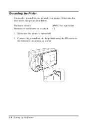
Connect the ground wire to be attached: 3.2 1. Make sure the wire meets the specification below. Thickness of wire: AWG 18 or equivalent Diameter of terminal to the printer using the FG screw on the bottom of the printer, as shown. 1-8 Setting Up the Printer Make sure the printer is turned off. 2. Grounding the Printer You need a ground wire to ground your printer.
Connect the ground wire to be attached: 3.2 1. Make sure the wire meets the specification below. Thickness of wire: AWG 18 or equivalent Diameter of terminal to the printer using the FG screw on the bottom of the printer, as shown. 1-8 Setting Up the Printer Make sure the printer is turned off. 2. Grounding the Printer You need a ground wire to ground your printer.
Operation Manual
Page 17
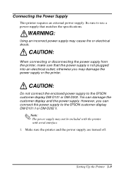
...the power supply is not plugged into an electrical outlet; CAUTION: Do not connect the enclosed power supply to the EPSON customer display DM-D101 II or DM-D202 II. Make sure the printer and the power supply are turned off. However, you may damage the power supply or the... display and the power supply. This can connect this power supply to the EPSON customer display DM-D101 or DM-D202. Setting Up the Printer 1-9 WARNING: Using an incorrect power supply may not be included with the printer with serial interface. 1. CAUTION: When connecting or disconnecting the power supply from...
...the power supply is not plugged into an electrical outlet; CAUTION: Do not connect the enclosed power supply to the EPSON customer display DM-D101 II or DM-D202 II. Make sure the printer and the power supply are turned off. However, you may damage the power supply or the... display and the power supply. This can connect this power supply to the EPSON customer display DM-D101 or DM-D202. Setting Up the Printer 1-9 WARNING: Using an incorrect power supply may not be included with the printer with serial interface. 1. CAUTION: When connecting or disconnecting the power supply from...
Operation Manual
Page 18
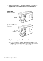
Plug the power supply's cord into the printer's connector as shown below. Plug the power supply's cable into an outlet. Model with Serial Interface Model with Parallel Interface 3. t If you ever need to remove the cable, unplug the power supply's cord from an outlet and then grasp the connector firmly at the arrow mark and pull it straight out. 1-10 Setting Up the Printer Note that the flat side of the connector faces down. 2.
Plug the power supply's cord into the printer's connector as shown below. Plug the power supply's cable into an outlet. Model with Serial Interface Model with Parallel Interface 3. t If you ever need to remove the cable, unplug the power supply's cord from an outlet and then grasp the connector firmly at the arrow mark and pull it straight out. 1-10 Setting Up the Printer Note that the flat side of the connector faces down. 2.
Operation Manual
Page 19
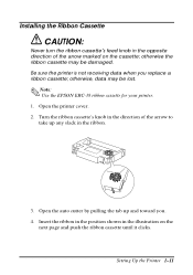
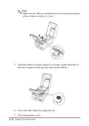
otherwise the ribbon cassette may be damaged. otherwise, data may be lost. Note: Use the EPSON ERC-38 ribbon cassette for your printer. 1. Insert the ribbon in the position shown in the ribbon. 3. Open the auto cutter by pulling the tab up any slack in the illustration on ...'s knob in the direction of the arrow marked on the next page and push the ribbon cassette until it clicks. Setting Up the Printer 1-11 Be sure the printer is not receiving data when you . 4. Installing the Ribbon Cassette CAUTION: Never turn the ribbon cassette's feed knob in the opposite direction of...
otherwise the ribbon cassette may be damaged. otherwise, data may be lost. Note: Use the EPSON ERC-38 ribbon cassette for your printer. 1. Insert the ribbon in the position shown in the ribbon. 3. Open the auto cutter by pulling the tab up any slack in the illustration on ...'s knob in the direction of the arrow marked on the next page and push the ribbon cassette until it clicks. Setting Up the Printer 1-11 Be sure the printer is not receiving data when you . 4. Installing the Ribbon Cassette CAUTION: Never turn the ribbon cassette's feed knob in the opposite direction of...
Operation Manual
Page 20
Close the printer cover. 1-12 Setting Up the Printer Close the auto cutter by using the tab. 7. Turn the ribbon cassette's knob 5 or 6 times in the direction of the arrow again to take up any slack in the ribbon. 6. Note: Make sure the ribbon is installed between the print head and the platen without wrinkles or creases. 5.
Close the printer cover. 1-12 Setting Up the Printer Close the auto cutter by using the tab. 7. Turn the ribbon cassette's knob 5 or 6 times in the direction of the arrow again to take up any slack in the ribbon. 6. Note: Make sure the ribbon is installed between the print head and the platen without wrinkles or creases. 5.
Operation Manual
Page 21
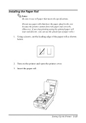
Insert the paper roll. Setting Up the Printer 1-13 Do not use the glued type of the paper roll as shown below. 2. Installing the Paper Roll Notes: Be sure to use roll paper that have the paper glued to the core because the printer cannot detect the paper end correctly. (However, if you stop printing using the optional paper roll near-end detector, you can use paper rolls that meets the specifications. Using scissors, cut the leading edge of paper rolls.) 1. Turn on the printer and open the printer cover. 3.
Insert the paper roll. Setting Up the Printer 1-13 Do not use the glued type of the paper roll as shown below. 2. Installing the Paper Roll Notes: Be sure to use roll paper that have the paper glued to the core because the printer cannot detect the paper end correctly. (However, if you stop printing using the optional paper roll near-end detector, you can use paper rolls that meets the specifications. Using scissors, cut the leading edge of paper rolls.) 1. Turn on the printer and open the printer cover. 3.
Operation Manual
Page 22
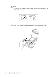
Open the auto cutter by pulling the tab up and toward you. 1-14 Setting Up the Printer Note: Be sure to note the correct direction that the paper comes off the roll as shown below. 4.
Open the auto cutter by pulling the tab up and toward you. 1-14 Setting Up the Printer Note: Be sure to note the correct direction that the paper comes off the roll as shown below. 4.
Operation Manual
Page 23
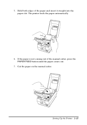
Hold both edges of the manual cutter, press the PAPER FEED button until the paper comes out. 7. Cut the paper on the manual cutter. If the paper is not coming out of the paper and insert it straight into the paper slot. Setting Up the Printer 1-15 The printer feeds the paper automatically. 6. 5.
Hold both edges of the manual cutter, press the PAPER FEED button until the paper comes out. 7. Cut the paper on the manual cutter. If the paper is not coming out of the paper and insert it straight into the paper slot. Setting Up the Printer 1-15 The printer feeds the paper automatically. 6. 5.
Operation Manual
Page 24
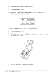
Close the auto cutter by using the tab. 9. Open the printer cover. 2. When the PAPER OUT light blinks, press the PAPER FEED button to set the printer on line. Pull up the paper and cut the paper at the dotted line shown in the illustration below . 1. Cut here 3. Close the printer cover. 10. To remove the paper roll, follow the steps below . 8. Remove the paper roll from the printer. 1-16 Setting Up the Printer
Close the auto cutter by using the tab. 9. Open the printer cover. 2. When the PAPER OUT light blinks, press the PAPER FEED button to set the printer on line. Pull up the paper and cut the paper at the dotted line shown in the illustration below . 1. Cut here 3. Close the printer cover. 10. To remove the paper roll, follow the steps below . 8. Remove the paper roll from the printer. 1-16 Setting Up the Printer


