
Operation Manual
Page 9
... the Printer Opening and Closing the Printer Cover 1-1 Unpacking 1-2 Removing the protective material 1-2 Connecting the Printer to Your Computer 1-3 TM-U950 1-3 TM-U950P 1-5 Connecting the Printer to the Drawer 1-5 Connecting to a Direct Connection Display Module 1-9 Grounding the Printer 1-10 Connecting the Power Supply 1-12...DIP Switches 1-20 DIP switch functions 1-23 Adjusting the Paper Near End Detectors 1-26 Using the Power Switch Cover 1-28 Chapter 2 Using the Printer Operating the Control Panel 2-1 Buttons 2-1 Indicator lights 2-2 Slip Paper Handling 2-3 Using the MICR...
... the Printer Opening and Closing the Printer Cover 1-1 Unpacking 1-2 Removing the protective material 1-2 Connecting the Printer to Your Computer 1-3 TM-U950 1-3 TM-U950P 1-5 Connecting the Printer to the Drawer 1-5 Connecting to a Direct Connection Display Module 1-9 Grounding the Printer 1-10 Connecting the Power Supply 1-12...DIP Switches 1-20 DIP switch functions 1-23 Adjusting the Paper Near End Detectors 1-26 Using the Power Switch Cover 1-28 Chapter 2 Using the Printer Operating the Control Panel 2-1 Buttons 2-1 Indicator lights 2-2 Slip Paper Handling 2-3 Using the MICR...

Operation Manual
Page 14
To use an interface cable that requires millimeter-type screws, replace the inch-type screws with inch-type hexagonal lock screws installed. Note: Your printer comes with the enclosed millimeter-type screws using a hex screwdriver (5 mm). Attach the other end of screws, see the figure below. The inch-type screw is on both sides of the cable connector. 2. To distinguish the two types of the cable to the computer. 4. Plug the power supply's power cord into an electrical outlet. 1-4 Setting Up the Printer Tighten the screws on the left. 3.
To use an interface cable that requires millimeter-type screws, replace the inch-type screws with inch-type hexagonal lock screws installed. Note: Your printer comes with the enclosed millimeter-type screws using a hex screwdriver (5 mm). Attach the other end of screws, see the figure below. The inch-type screw is on both sides of the cable connector. 2. To distinguish the two types of the cable to the computer. 4. Plug the power supply's power cord into an electrical outlet. 1-4 Setting Up the Printer Tighten the screws on the left. 3.

Operation Manual
Page 15
Plug the power supply's power cord into the printer's interface connector. 2. Setting Up the Printer 1-5 Make sure that matches the printer specification. Attach the other end of the cable to the printer's built-in interface. 1. TM-U950P You need an appropriate parallel interface cable to connect your computer to the computer. 3. Using an improper drawer may damage the drawer as...
Plug the power supply's power cord into the printer's interface connector. 2. Setting Up the Printer 1-5 Make sure that matches the printer specification. Attach the other end of the cable to the printer's built-in interface. 1. TM-U950P You need an appropriate parallel interface cable to connect your computer to the computer. 3. Using an improper drawer may damage the drawer as...
Operation Manual
Page 22
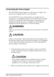
Connecting the Power Supply The TM-U950P printer requires an external power supply. CAUTION: When connecting or disconnecting the power supply from the printer, make sure that the voltage required by the intelligent module. When the printer is connected to an intelligent module, the power is supplied by the power supply matches that the power supply is recommended. CAUTION: If the power supply's rated voltage and your outlet's voltage do...
Connecting the Power Supply The TM-U950P printer requires an external power supply. CAUTION: When connecting or disconnecting the power supply from the printer, make sure that the voltage required by the intelligent module. When the printer is connected to an intelligent module, the power is supplied by the power supply matches that the power supply is recommended. CAUTION: If the power supply's rated voltage and your outlet's voltage do...

Operation Manual
Page 23
TM-U950 TM-U950P Setting Up the Printer 1-13 Notice that the flat side of the plug faces down. Plug in the power supply's cable as shown below. 3.
TM-U950 TM-U950P Setting Up the Printer 1-13 Notice that the flat side of the plug faces down. Plug in the power supply's cable as shown below. 3.

Operation Manual
Page 38
If you want to use the enclosed power switch cover to make sure that the power switch is attached, unplug the power supply cord from the outlet immediately. 1-28 Setting Up the Printer Using the Power Switch Cover You can use this cover, install it as shown in the illustration below. WARNING: If an accident occurs when the power switch cover is not accidentally pressed.
If you want to use the enclosed power switch cover to make sure that the power switch is attached, unplug the power supply cord from the outlet immediately. 1-28 Setting Up the Printer Using the Power Switch Cover You can use this cover, install it as shown in the illustration below. WARNING: If an accident occurs when the power switch cover is not accidentally pressed.

Operation Manual
Page 46
...to help you close the printer cover if one or both of the OPEN LOCK levers is open. Troubleshooting 3-1 If the outlet is printed. See the illustration on . Make sure that the power supply cables are off, make sure that power is supplied to the power outlet. Install a new ...paper roll. Press the round indentation on , a paper roll is not installed or is on the printer cover until the cover audibly clicks into the printer, the power unit, and to the power outlet....
...to help you close the printer cover if one or both of the OPEN LOCK levers is open. Troubleshooting 3-1 If the outlet is printed. See the illustration on . Make sure that the power supply cables are off, make sure that power is supplied to the power outlet. Install a new ...paper roll. Press the round indentation on , a paper roll is not installed or is on the printer cover until the cover audibly clicks into the printer, the power unit, and to the power outlet....

Specifications
Page 13
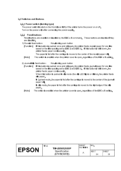
... 2.1.3 Notes on setting DIP switch 2-5 to ON 17-4 2.1.4 Reception of status from the printer through the bidirectional parallel interface ...17-5 2.2 Connectors ...18 2.2.1 Interface connectors 18 2.2.2 Power supply connector 18 2.2.3 Drawer kick-out connector (modular connector 19 2.2.4 Customer display connector (For RS-232 serial interface 21 TITLE TM-U950/U950P Specification (STANDARD) SHEET REVISION AF NO.
... 2.1.3 Notes on setting DIP switch 2-5 to ON 17-4 2.1.4 Reception of status from the printer through the bidirectional parallel interface ...17-5 2.2 Connectors ...18 2.2.1 Interface connectors 18 2.2.2 Power supply connector 18 2.2.3 Drawer kick-out connector (modular connector 19 2.2.4 Customer display connector (For RS-232 serial interface 21 TITLE TM-U950/U950P Specification (STANDARD) SHEET REVISION AF NO.

Specifications
Page 36
...When the power is proceeded in the Nibble or Byte mode. · Description This mode allows data transmission from the printer to the host is turned on -line/off -line The printer is not equipped with any on or until the printer becomes ready ... from the asynchronous printer under the control of the host. TITLE EPSON TM-U950/U950P Specification (STANDARD) SHEET NO. The printer is placed into off-line status in units of Electrical and Electronic Engineers, Inc. 1) Specifications Data transmission: 8-bit Parallel Synchronization: Externally supplied nStrobe signals Handshaking...
...When the power is proceeded in the Nibble or Byte mode. · Description This mode allows data transmission from the printer to the host is turned on -line/off -line The printer is not equipped with any on or until the printer becomes ready ... from the asynchronous printer under the control of the host. TITLE EPSON TM-U950/U950P Specification (STANDARD) SHEET NO. The printer is placed into off-line status in units of Electrical and Electronic Engineers, Inc. 1) Specifications Data transmission: 8-bit Parallel Synchronization: Externally supplied nStrobe signals Handshaking...
Specifications
Page 42
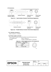
2.2 Connectors 2.2.1 Interface connectors Refer to Section 2.1, Interface 2.2.2 Power supply connector This connector is used to connect the printer to an external power source. 1) Pin assignments: Refer to Table 2.2.1. 2) Model: Hosiden TCS7960-532010 or equivalent Table 2.2.1 Pin Number 1 2 3 Shell Power Supply Connector Pin Assignments Signal Name +24 VDC GND NC Frame GND TITLE EPSON TM-U950/U950P Specification (STANDARD) SHEET NO. REVISION AD NEXT 2169 SHEET 2158
2.2 Connectors 2.2.1 Interface connectors Refer to Section 2.1, Interface 2.2.2 Power supply connector This connector is used to connect the printer to an external power source. 1) Pin assignments: Refer to Table 2.2.1. 2) Model: Hosiden TCS7960-532010 or equivalent Table 2.2.1 Pin Number 1 2 3 Shell Power Supply Connector Pin Assignments Signal Name +24 VDC GND NC Frame GND TITLE EPSON TM-U950/U950P Specification (STANDARD) SHEET NO. REVISION AD NEXT 2169 SHEET 2158

Specifications
Page 44
Otherwise, an overcurrent could damage the solenoid. TITLE EPSON TM-U950/U950P Specification (STANDARD) SHEET NO. The resistance of the drawer kick-out solenoid must not be less than that specified (24 W). 4) Drawer open/close signal Input signal lever (connector pin 3): "L" = 0 to 0.8 V "H" = 2 to use the printer power supply (connector pin 4) for the drawer connector cable. 2. Be sure...
Otherwise, an overcurrent could damage the solenoid. TITLE EPSON TM-U950/U950P Specification (STANDARD) SHEET NO. The resistance of the drawer kick-out solenoid must not be less than that specified (24 W). 4) Drawer open/close signal Input signal lever (connector pin 3): "L" = 0 to 0.8 V "H" = 2 to use the printer power supply (connector pin 4) for the drawer connector cable. 2. Be sure...
Specifications
Page 58
... paper for one line based on the power only after connecting the power supply. 3.3.2 Panel buttons Panel buttons are disabled. NEXT A 34 SHEET 33 If this button is held down , the printer feeds paper continuously. If this button is held down , the printer feeds paper continuously. TITLE EPSON TM-U950/U950P Specification (STANDARD) SHEET REVISION NO. When this...
... paper for one line based on the power only after connecting the power supply. 3.3.2 Panel buttons Panel buttons are disabled. NEXT A 34 SHEET 33 If this button is held down , the printer feeds paper continuously. If this button is held down , the printer feeds paper continuously. TITLE EPSON TM-U950/U950P Specification (STANDARD) SHEET REVISION NO. When this...
Specifications
Page 62
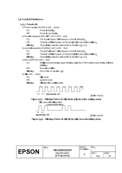
...is sufficient paper on the receipt side (normal condition). 3.4 Panel LED Indicators 3. 4. 1 Panel LED 1) Power supply (POWER) LED: Green On: Power is sufficient paper on the journal side (normal condition). Blinking: Test printing standby state (refer to Section 3.8)... insertion waiting state) Slip removal waiting state [Units: msec] Figure 3.4.2 Blinking Pattern in Slip Mode (slip removal waiting state) TITLE EPSON TM-U950/U950P Specification (STANDARD) SHEET REVISION NO. Blinking: Test printing standby state (refer to Section 3.5 - 3)) 4) Error (ERROR) LED: ...
...is sufficient paper on the receipt side (normal condition). 3.4 Panel LED Indicators 3. 4. 1 Panel LED 1) Power supply (POWER) LED: Green On: Power is sufficient paper on the journal side (normal condition). Blinking: Test printing standby state (refer to Section 3.8)... insertion waiting state) Slip removal waiting state [Units: msec] Figure 3.4.2 Blinking Pattern in Slip Mode (slip removal waiting state) TITLE EPSON TM-U950/U950P Specification (STANDARD) SHEET REVISION NO. Blinking: Test printing standby state (refer to Section 3.5 - 3)) 4) Error (ERROR) LED: ...

Specifications
Page 68
...: Stops all printer operations. Blinks the ERROR LED. 3.8.3 Data receive error If one of DIP switch 1-7. Impossible to recover. NOTE: When any error shown above occurs, turn off -line. Parity error Framing error Overrun error TITLE EPSON TM-U950/U950P Specification (STANDARD) SHEET REVISION NO. Impossible to recover. Low voltage error The power supply voltage is...
...: Stops all printer operations. Blinks the ERROR LED. 3.8.3 Data receive error If one of DIP switch 1-7. Impossible to recover. NOTE: When any error shown above occurs, turn off -line. Parity error Framing error Overrun error TITLE EPSON TM-U950/U950P Specification (STANDARD) SHEET REVISION NO. Impossible to recover. Low voltage error The power supply voltage is...
Specifications
Page 75
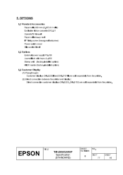
... Exclusive ribbon cassette ERC-31 Operator's Manual Paper roll take-up reel I/F fixing screw (hexagonal setscrew) Power switch cover Slip caution label 5.2 Options External power supply PS-150 Journal lock with keys: JL-950 Stamp unit (factory-installed option) MICR reader (factory-installed... Customer displays DM-D202II and DM-D101II are sold separately from the printer. (2) Direct connection between the printer and display: Direct connection customer displays DM-D203, DM-D102 are sold separately from the printer. TITLE EPSON TM-U950/U950P Specification (STANDARD) SHEET REVISION NO. 5.
... Exclusive ribbon cassette ERC-31 Operator's Manual Paper roll take-up reel I/F fixing screw (hexagonal setscrew) Power switch cover Slip caution label 5.2 Options External power supply PS-150 Journal lock with keys: JL-950 Stamp unit (factory-installed option) MICR reader (factory-installed... Customer displays DM-D202II and DM-D101II are sold separately from the printer. (2) Direct connection between the printer and display: Direct connection customer displays DM-D203, DM-D102 are sold separately from the printer. TITLE EPSON TM-U950/U950P Specification (STANDARD) SHEET REVISION NO. 5.
Specifications
Page 136
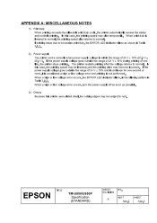
... V ± 10% (21.6 V 26.4 V). If printing stops due to normal. TITLE EPSON TM-U950/U950P Specification (STANDARD) SHEET REVISION NO. When a high or low voltage error occurs, the ERROR LED indicator blinks, in the blinking pattern in Table 3.8.1. 2) Power supply The printer works correctly when power supply voltage is within the range of 24 V ± 10% and it...
... V ± 10% (21.6 V 26.4 V). If printing stops due to normal. TITLE EPSON TM-U950/U950P Specification (STANDARD) SHEET REVISION NO. When a high or low voltage error occurs, the ERROR LED indicator blinks, in the blinking pattern in Table 3.8.1. 2) Power supply The printer works correctly when power supply voltage is within the range of 24 V ± 10% and it...
Specifications
Page 141
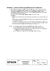
... be used , the resulting overcurrent may damage the device. (*4) Connecting power supply other than that use the drawer kick-out connector. Never connect any other devices that specified voids the warranty. TITLE EPSON TM-U950/U950P Specification (STANDARD) SHEET REVISION NO. APPENDIX E: NOTES ON USING THE ... 1 A or less. (*3) Be sure to use drawer kick-out connector pin 4 (24 V power output) to the drawer kick-out connector. (*4) NOTES: (*1) Operating the printer with incorrectly installed devices voids the warranty. (*2) Connecting devices other than the drawer open /close signal is...
... be used , the resulting overcurrent may damage the device. (*4) Connecting power supply other than that use the drawer kick-out connector. Never connect any other devices that specified voids the warranty. TITLE EPSON TM-U950/U950P Specification (STANDARD) SHEET REVISION NO. APPENDIX E: NOTES ON USING THE ... 1 A or less. (*3) Be sure to use drawer kick-out connector pin 4 (24 V power output) to the drawer kick-out connector. (*4) NOTES: (*1) Operating the printer with incorrectly installed devices voids the warranty. (*2) Connecting devices other than the drawer open /close signal is...

